If you wish to contribute or participate in the discussions about articles you are invited to contact the Editor
CBCS Modulation: Difference between revisions
Rui.Pereira (talk | contribs) |
Gema.Cueto (talk | contribs) No edit summary |
||
| (5 intermediate revisions by 2 users not shown) | |||
| Line 6: | Line 6: | ||
|Title={{PAGENAME}} | |Title={{PAGENAME}} | ||
}} | }} | ||
== CBCS Modulation | == Composite Binary Coded Symbols (CBCS) Modulation: Definition and Analysis of Performance == | ||
On June 26th, 2004, the United States of America and the European Union signed the Agreement on the promotion, provision and use of Galileo and GPS satellite-based navigation systems and related applications [G.W. Hein et al., 2005]<ref name="GH_2005">[G.W. Hein et al., 2005] G.W. Hein, J.-A. Avila-Rodriguez, L. Ries, L. Lestarquit, J.-L. Issler, J. Godet, A.R. Pratt, Members of the Galileo Signal Task Force of the European Commission: A Candidate for the Galileo L1 OS Optimized Signal, Proceedings of the International Technical Meeting of the Institute of Navigation, ION-GNSS 2005, 13-16 September, 2005, Long Beach, California, USA.</ref>. Among other topics it was decided to adopt a common baseline signal to be transmitted by both the [[GALILEO Signal Plan|Galileo E1 Open Service (OS)]] and the future [[GPS Signal Plan|GPS L1 Civil signal (L1C)]] on E1/L1. Although the agreement fixed [[Binary Offset Carrier (BOC)|BOC(1,1)]] as the baseline for both Galileo E1 OS and the GPS future L1C signals, it left the door open for a possible optimization of that signal considering the overall framework conditions of the agreement. | On June 26th, 2004, the United States of America and the European Union signed the Agreement on the promotion, provision and use of Galileo and GPS satellite-based navigation systems and related applications [G.W. Hein et al., 2005]<ref name="GH_2005">[G.W. Hein et al., 2005] G.W. Hein, J.-A. Avila-Rodriguez, L. Ries, L. Lestarquit, J.-L. Issler, J. Godet, A.R. Pratt, Members of the Galileo Signal Task Force of the European Commission: A Candidate for the Galileo L1 OS Optimized Signal, Proceedings of the International Technical Meeting of the Institute of Navigation, ION-GNSS 2005, 13-16 September, 2005, Long Beach, California, USA.</ref>. Among other topics it was decided to adopt a common baseline signal to be transmitted by both the [[GALILEO Signal Plan|Galileo E1 Open Service (OS)]] and the future [[GPS Signal Plan|GPS L1 Civil signal (L1C)]] on E1/L1. Although the agreement fixed [[Binary Offset Carrier (BOC)|BOC(1,1)]] as the baseline for both Galileo E1 OS and the GPS future L1C signals, it left the door open for a possible optimization of that signal considering the overall framework conditions of the agreement. | ||
| Line 17: | Line 17: | ||
where <math>\alpha</math> and <math>\beta</math> indicate the amount of power that is put on BOC(1,1) and on the BCS signal with respect to the total OS power of the signal. Thus, <math>\alpha</math> and <math>\beta</math> fulfil the condition <math>\alpha | where <math>\alpha</math> and <math>\beta</math> indicate the amount of power that is put on BOC(1,1) and on the BCS signal with respect to the total OS power of the signal. Thus, <math>\alpha</math> and <math>\beta</math> fulfil the condition <math>\alpha + \beta = 1</math>. For this same reason, we will use in other parts of the thesis <math>\beta = \rho</math> and <math>\alpha = 1 - \rho</math> instead. Moreover, [s] represents the BCS vector as defined in [[Multilevel Coded Spreading Symbols (MCS)]]. As we saw there, BCS is a generalization of the [[Binary Phase Shift Keying Modulation (BPSK)|BPSK]] and [[Binary Offset Carrier (BOC)|BOC]] modulations. In addition, it is important to realize that the CBCS definition intrinsically assumes the use of Interplex to multiplex the signals. | ||
The flexibility of the CBCS approach lies in the fact that it could be easily converted into another CBCS by changing the contribution of the BCS part or even choosing different chip rates. In fact, a particular case of the CBCS solution is the pure BCS signal which seems to present the best performance in terms of multipath for selected sequences. Nonetheless, for the EU developers keeping high interoperability with BOC(1,1) receivers was a mandatory from the very beginning and this forced the design to have an important amount of BOC(1,1) in the definition. | The flexibility of the CBCS approach lies in the fact that it could be easily converted into another CBCS by changing the contribution of the BCS part or even choosing different chip rates. In fact, a particular case of the CBCS solution is the pure BCS signal which seems to present the best performance in terms of multipath for selected sequences. Nonetheless, for the EU developers keeping high interoperability with BOC(1,1) receivers was a mandatory from the very beginning and this forced the design to have an important amount of BOC(1,1) in the definition. | ||
| Line 175: | Line 175: | ||
being | being <math>\rho</math> the percentage of power on the BCS component, as we saw above. According to this, we can express the power spectral density of the CBCS([s],1,%) modulation as follows: | ||
::[[File: CBCS_Eq_16.png|none|640px]] | ::[[File: CBCS_Eq_16.png|none|640px]] | ||
| Line 231: | Line 231: | ||
::::[[File:CBCS_Fig_12.png|none|thumb|420px|'''''Figure 12:''''' Cramér Rao Lower Bound of E1 OS signals. It must be noted that | ::::[[File:CBCS_Fig_12.png|none|thumb|420px|'''''Figure 12:''''' Cramér Rao Lower Bound of E1 OS signals. It must be noted that <math>OS_A</math> refers to the data channel while <math>OS_B</math> refers to the pilot channel.]] | ||
| Line 254: | Line 254: | ||
with <math>\left (i,j \right ) \in \left \{1,2,\cdots,N \right \} \times \left \{1,2,\cdots,N \right \}</math. Furthermore, the Barankin bound on the covariance < | with <math>\left (i,j \right ) \in \left \{1,2,\cdots,N \right \} \times \left \{1,2,\cdots,N \right \}</math>. Furthermore, the Barankin bound on the covariance <math>Cov[\hat{x}\left(r\right)]</math> for the parameter x based on the measurements r is given by: | ||
::[[File: CBCS_Eq_26.png|none|320px]] | ::[[File: CBCS_Eq_26.png|none|320px]] | ||
| Line 267: | Line 267: | ||
Finally, we must underline that the Barankin bound is more accurate than the Cramér Rao lower bound as shown in [R. McAulay and E. Hofstetter, 1971]<ref>[R. McAulay and E. Hofstetter, 1971] R. McAulay and E. Hofstetter, Barankin Bounds on Parameter Estimation, IEEE Transactions on Information Theory, vol. IT-17, number 6, pp. 669-676, 1971.</ref>. In fact, the Barankin bound can be made tighter than the Cramér-Rao bound provided the correct test points are chosen. Moreover, the Barankin bound can be applied in general to more cases than the Cramér Rao bound under the assumption that we have some a priori knowledge on the conditional probability of some particular points. As one can imagine, this information is not always available and justifies the common use of the Cramér Rao lower bound instead. | Finally, we must underline that the Barankin bound is more accurate than the Cramér Rao lower bound as shown in [R. McAulay and E. Hofstetter, 1971]<ref>[R. McAulay and E. Hofstetter, 1971] R. McAulay and E. Hofstetter, Barankin Bounds on Parameter Estimation, IEEE Transactions on Information Theory, vol. IT-17, number 6, pp. 669-676, 1971.</ref>. In fact, the Barankin bound can be made tighter than the Cramér-Rao bound provided the correct test points are chosen. Moreover, the Barankin bound can be applied in general to more cases than the Cramér Rao bound under the assumption that we have some a priori knowledge on the conditional probability of some particular points. As one can imagine, this information is not always available and justifies the common use of the Cramér Rao lower bound instead. | ||
== CBCS Interference Performance == | == CBCS Interference Performance == | ||
| Line 339: | Line 338: | ||
==References== | ==References== | ||
<references/> | <references/> | ||
== Credits == | |||
The information presented in this NAVIPEDIA’s article is an extract of the PhD work performed by Dr. Jose Ángel Ávila Rodríguez in the FAF University of Munich as part of his Doctoral Thesis “On Generalized Signal Waveforms for Satellite Navigation” presented in June 2008, Munich (Germany) | |||
[[Category:Fundamentals]] | [[Category:Fundamentals]] | ||
[[Category:GNSS Signals]] | [[Category:GNSS Signals]] | ||
Latest revision as of 11:46, 20 October 2022
| Fundamentals | |
|---|---|
| Title | CBCS Modulation |
| Author(s) | J.A Ávila Rodríguez, University FAF Munich, Germany. |
| Level | Advanced |
| Year of Publication | 2011 |
Composite Binary Coded Symbols (CBCS) Modulation: Definition and Analysis of Performance
On June 26th, 2004, the United States of America and the European Union signed the Agreement on the promotion, provision and use of Galileo and GPS satellite-based navigation systems and related applications [G.W. Hein et al., 2005][1]. Among other topics it was decided to adopt a common baseline signal to be transmitted by both the Galileo E1 Open Service (OS) and the future GPS L1 Civil signal (L1C) on E1/L1. Although the agreement fixed BOC(1,1) as the baseline for both Galileo E1 OS and the GPS future L1C signals, it left the door open for a possible optimization of that signal considering the overall framework conditions of the agreement.
Right after the Agreement was signed, experts on both sides of the Atlantic started to work on possible solutions that would fulfil the criteria set up in the Agreement. The solution would have to clearly outperform the agreed BOC(1,1). Finally, in September 2005 a first tentative solution, known as CBCS(20) was presented by members of the Signal Task Force (STF) of the European Commission (EC) [G.W. Hein et al., 2005] [1]. The proposed solution was highly interoperable with the baseline BOC(1,1) and offered at the same time the possibility to have superior performance to high precision receivers with wider bandwidths.
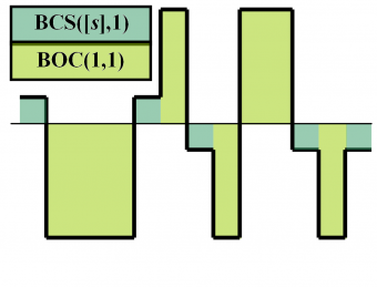
The CBCS modulation (Composite Binary Coded Symbols) is the result of superposing BOC(1,1) and a BCS (Binary Coded Symbol) waveform with the same chip rate, according to the following expression:
where [math]\displaystyle{ \alpha }[/math] and [math]\displaystyle{ \beta }[/math] indicate the amount of power that is put on BOC(1,1) and on the BCS signal with respect to the total OS power of the signal. Thus, [math]\displaystyle{ \alpha }[/math] and [math]\displaystyle{ \beta }[/math] fulfil the condition [math]\displaystyle{ \alpha + \beta = 1 }[/math]. For this same reason, we will use in other parts of the thesis [math]\displaystyle{ \beta = \rho }[/math] and [math]\displaystyle{ \alpha = 1 - \rho }[/math] instead. Moreover, [s] represents the BCS vector as defined in Multilevel Coded Spreading Symbols (MCS). As we saw there, BCS is a generalization of the BPSK and BOC modulations. In addition, it is important to realize that the CBCS definition intrinsically assumes the use of Interplex to multiplex the signals.
The flexibility of the CBCS approach lies in the fact that it could be easily converted into another CBCS by changing the contribution of the BCS part or even choosing different chip rates. In fact, a particular case of the CBCS solution is the pure BCS signal which seems to present the best performance in terms of multipath for selected sequences. Nonetheless, for the EU developers keeping high interoperability with BOC(1,1) receivers was a mandatory from the very beginning and this forced the design to have an important amount of BOC(1,1) in the definition.
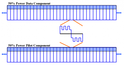
We show next graphically the signal generation of CBCS in the time domain. It is important to note that CBCS is not a binary signal but two binary signals in anti-phase in data and pilot.
Signal waveforms with a very sharp peak were the goal of the optimization carried out in the past years for both GPS and Galileo. Indeed, as we have shown in Autocorrelation & Power Spectral Density, by selecting [math]\displaystyle{ p_{T_c}\left (t \right ) }[/math] with good aperiodic correlation, important improvements in terms of performance can be obtained, especially regarding multipath. In the course of the optimization other interesting solutions were found with even different chip rates than those of the Agreement. Nevertheless, the important constraint to be compliant with BOC(1,1) limited the candidates to have a chip rate of 1 MHz, as we have already underlined.
Unlike the MBOC, the CBCS modulation was proposed alone from the European side. Thus, to the signal definition of the equation (1) above the extra constraint to use the Interplex modulation scheme was added in the definition in light with the development of other signals in the Galileo satellites. Indeed, the CBCS modulation is defined as the superposition of a BOC signal with a BCS using a modified and optimized Interplex scheme in the navigation payload of the satellite.
CBCS Time Domain Representation and Spectrum
The CBCS signal features a spread-spectrum signal with 4-level sub-carriers, whereas the BOC or BCS signals feature only binary sub-carriers. As we will show in detail in Signal Multiplex Techniques for GNSS , an implementation of the CBCS signals on the Galileo E1 modulation could have been performed using other multiplexing schemes such as the FH-Interplex (Faded-Harmonics) [CNES, 2005][2], as this also relies on the sum of two 4-level spread-spectrum signals.
Yet, the analysis of the FH-Interplex scheme for the CBCS put in evidence two important drawbacks [G.W. Hein et al., 2005] [1] :
- The inter-modulation product relative power of the FH-Interplex that results from applying CBCS is increased resulting thus in an important loss of efficiency
- The quadrature component suffers from important distortions which may induce unacceptable losses on the receiver, as well as an increased spreading of the quadrature signal in adjacent frequency bands. In the case of Galileo, the degraded signal would be the PRS what supposed an important drawback.
As a solution, a new modulation scheme was developed in [L. Ries et al., 2006][3] to provide an optimized implementation of the CBCS signals, without the drawbacks described in the preceding lines. The resulting modulation is more efficient than the Modified Hexaphase as it reduces significantly the effect and power of the inter-modulation product.
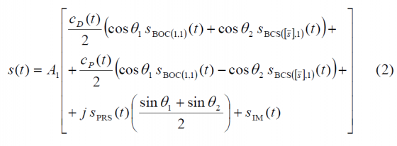
As shown in Power Spectral Density of the CBCS Modulation, the generic CBCS baseband modulation can be expressed mathematically as follows:
where:
- [math]\displaystyle{ A_1 }[/math] is the amplitude of the modulation envelope, sum of the OS data (D) and pilot (P), PRS and Inter-Modulation product IM. The maximum possible value of [math]\displaystyle{ A_1 }[/math] that respects the Agreement of 2004 is a function of the percentage of power put on the BCS component of the signal and the spectral relationship between BOC(1,1) and BCS. Moreover, [math]\displaystyle{ A_1 = sqrt{2P_t} }[/math] where [math]\displaystyle{ P_T }[/math] is the total power of the multiplexed signal.
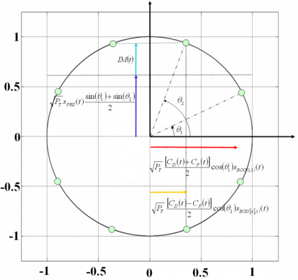
- [math]\displaystyle{ \theta_1 }[/math] and [math]\displaystyle{ \theta_2 }[/math] describe the angular distance of points of the 8-PSK modulation as described in Figure 2. This depends on the percentage of power that is placed on BCS.
- [math]\displaystyle{ S_{BOC \left( 1,1 \right )}\left ( t \right ) }[/math] represents the BOC(1,1) modulation with chip rate of 1.023 MHz
- [math]\displaystyle{ S_{BCS \left( [1],1 \right )}\left ( t \right ) }[/math] represents the BCS([s],1) modulation with a chip rate of 1.023 MHz and a BCS vector given by [s].
- [math]\displaystyle{ S_{PRS}\left ( t \right ) }[/math] is the PRS modulation ::* [math]\displaystyle{ BOC_{cos}\left ( 15,2.5 \right ) }[/math] BOCcos(15,2.5)
- [math]\displaystyle{ S_{IM}\left ( t \right ) }[/math] is the Inter-Modulation product signal
- [math]\displaystyle{ C_{D}\left ( t \right ) }[/math] and [math]\displaystyle{ C_{P}\left ( t \right ) }[/math] are the data and pilot codes respectively. It is important to note that [math]\displaystyle{ C_{D}\left ( t \right ) }[/math] also includes the data bits.
The phase points of the resulting constellation are shown in the following figure:
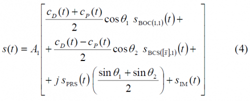
The modulation can be optimized so as to pseudo-randomly time-multiplex the BOC and BCS sub-carriers on the in-phase component. Rearranging the terms of (2) to make this pseudo-random time-multiplexing appear yields to the following expression:
If we look at the previous equation in detail, we can observe that the BOC(1,1) sub-carrier of the [math]\displaystyle{ OS_D }[/math] (Data) and [math]\displaystyle{ OS_P }[/math] (Pilot) components is transmitted during the same time-slots as it was on the original Hexaphase modulation with only BOC(1,1). In addition, the BCS sub-carrier of the [math]\displaystyle{ OS_D }[/math] (Data) and [math]\displaystyle{ OS_P }[/math] components is transmitted in time-slots complementary to those of the BOC sub-carrier (i.e in the time slot when the Modified Hexaphase in-phase component was equal to zero and therefore nothing was transmitted). As a result, the IM product is considerably reduced and 8 phase points appear instead of only 6. Also important to note is that the quadrature component (the PRS signal) is left unaffected by this new scheme, except for its relative amplitude.
Another important conclusion that we can draw from observing the equation above is that if one optimizes the data and pilot channel codes with each other, the code structure that results from applying the multiplexing scheme of (4) does not necessarily have to be also optimized in the general case.
Indeed, we can clearly recognize that the code that actually modulates the BOC(1,1) signal waveform is the semi-sum of the data and pilot codes. Equally, the semi-difference of the data and pilot codes modulates the BCS sequence. Moreover, these codes are not binary since they can take the values +2, 0 and -2 [P.G. Mattos, 2005][4]. As shown in [F. Soualle et al., 2005][5] the data and pilot codes were optimized without accounting for the modulation scheme. The consequence of this is that unless the receiver applies a coherent processing of the incoming signal, the codes will show a slight degradation.
Another very important aspect from the CBCS modulation is the power distribution, since this determines in the end the multipath rejection potential of the solutions. As shown in Power Spectral Density of the CBCS Modulation, the following expressions for the data and pilot channels can be derived:
where the parameter r represents the correlation between BOC(1,1) and the BCS signal:
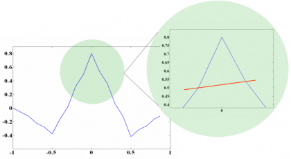
This parameter is of great importance as we will see when we describe the MBOC modulation in the next chapter. In fact, the BCS sequence of the CBCS was selected among other reasons because its value of r is zero. However, the cross-correlation of the CBCS signal with a BOC(1,1) alone receiver is not zero anymore and presents a so-called tracking bias. Indeed, this was the main drawback of the CBCS solution with respect to the finally selected MBOC. We show in the next figure the cross-correlation of the CBCS signal with BOC(1,1):
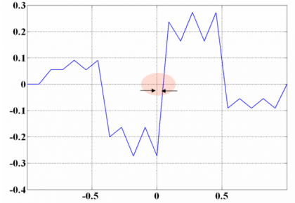
Indeed, this asymmetry leads to the mentioned tracking bias, as can be seen in the next figure:
We will talk a little bit more on this bias at the end of this chapter. Nevertheless, it is important to mention here that although there are solutions to eliminate the tracking bias that results from the non-zero correlation between CBCS and BOC(1,1), the need to have a signal that would not present such a disadvantage was the main reason that lead to moving to the finally selected CBOC solution. CBOC is a particular implementation of MBOC where the Interplex multiplex is part of the definition. Furthermore, CBOC can also be seen as a particular case of CBCS where the selected BCS is BOC(6,1).
A figure of great interest to analyze the impact of the CBCS modulation on a BOC(1,1) receiver is given by the cross-correlation that a receiver would suffer if it would only track the BOC(1,1) component of the CBCS signal.
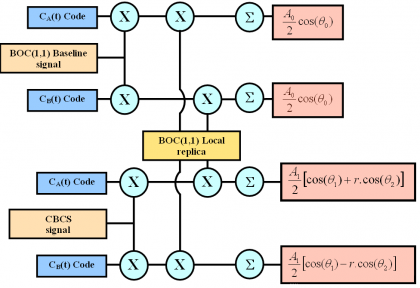
As shown in [G.W. Hein et al., 2005] [1], the delta correlation losses with respect to the baseline BOC(1,1) are the difference between the cross-correlation measured when the input is CBCS and the result of the auto-correlation when the input is a BOC(1,1) signal. Figure 6 below shows in detail the scheme assumed to measure the correlation losses.
The driving idea behind this model is to measure the real delta correlation losses that a receiver would experience if instead of the baseline BOC(1,1), the CBCS were emitted. It must be noted that while CBCS will of course not correlate 100 % with a BOC(1,1) replica as BOC(1,1) would do, resulting thus in losses, the more efficient CBCS modulation that results from reducing the IM product allows for higher receiver powers at user level for the same transmitted power from the satellite. Both figures go in opposite directions and must be considered together. Indeed, as shown in [G.W. Hein et al., 2005] [1], the delta correlation losses are shown to be:
When we express it in dB, the three contributions to the delta correlation losses can be clearly separated as follows:
where
[math]\displaystyle{ \Delta L_{Envelope_Power} }[/math] accounts for the fact that the amplitude of the baseline interplex modulation and that of the optimized signal differ slightly. Additionally, the term [math]\displaystyle{ \Delta L_{BOC \left (1,1 \right ) Power_Share} }[/math] represents the losses of power of the BOC(1,1) signal since part of it goes now to the BCS component and finally the third term [math]\displaystyle{ \Delta L_{Mismatch_Loss} }[/math] of the correlation losses is a function of the correlation between the chosen BCS([s],1) and BOC(1,1) and gives an idea of how similar to BOC(1,1) the CBCS signal is. If we look at the correlation term more in detail,
we can see that this contribution to the correlation losses can be eliminated by two means. The first one is doing [math]\displaystyle{ \theta_2 = \frac{\pi}{2} }[/math] what corresponds to the case of pure BOC(1,1). The other possibility and of much more interest is to have what leads to a CBCS solution with zero mismatch correlation losses. For reasons of implementation due to symmetry, special attention was paid to the solutions with .
Now that we have shown the mathematical background behind the CBCS modulation, we are ready to introduce the signal that for some time was the most interesting candidate of Galileo to substitute BOC(1,1) until CBOC came: namely CBCS. CBOC is the European implementation of MBOC.
CBCS([1,-1,1,-1,1,-1,1,-1,1,1], 1, 20 %)
After signing the Agreement of 2004 and as a result of long months of hard work, a BCS sequence was found to be an interesting candidate for the Galileo E1 OS signal. The selected BCS sequence was compatible to a very high degree with pure BOC(1,1) receivers [G.W. Hein et al., 2005] [1] while it offered at the same time an important potential to improve the positioning performance and to mitigate multipath. Moreover, the selected signal was compliant with the Agreement of 2004 and did not require important changes in the satellite payload. The BCS sequence was [s] = [1, -1, 1, -1, 1, -1, 1, -1, 1, 1] and the amount of power on the BCS sequence with respect to the total OS power was selected to be 20 % at user level what would corresponds to approximately 26 % at generation in the satellite. For simplicity, the signal was thus baptized with the name CBCS([1, -1, 1, -1, 1, -1, 1, -1, 1, 1], 1, 20 %) or CBCS(20) for short. The selected BCS sequence can be seen as a quasi BOC(5,1). Indeed, in terms of performance it was very similar to a BOC(5,1) but had a more favourable spectral distribution since it did not overlap the M-Code as much as the last one.
As we have said above, the CBCS modulation had a minimum impact on the payload, what made the solution a serious alternative. In addition a number of advantages can be identified:
- Compared with the original Interplex using only BOC(1,1), the CBCS modulation is more efficient, reducing the IM product power by more than 3dB.
- As a result, the optimized modulation offered an additional margin of 0.26 dB on the link budget, for the same transmitted power at satellite level.
- The modulation is fully compatible with a flexible signal generator implementation based on modulation tables with a high number of bits of quantization.
- Finally, in spite of having two additional phase points closer to each other, the CBCS modulation is less sensitive to payload phase noise than the original modulation.
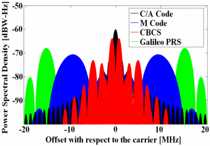
The following figure shows in detail how the Galileo and GPS Signal Plan would have looked like if the CBCS signal had been selected instead of MBOC.
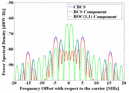
In the next figure we show in detail the power distribution of the spectra of the different components of the CBCS modulation:
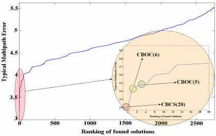
An important number of constraints were introduced during the search of the best potential signal candidate for the Galileo E1 OS to substitute BOC(1,1). Finally among all the solutions that passed the selected criteria, the best candidate was chosen. One of the most important performance merit figures for the final selection was the multipath performance for a given bandwidth (12 MHz) since this was considered to be the most important source of error due to its unpredictable properties. Furthermore 12 MHz was thought to be a reasonable bandwidth for future receivers even in the field of mass market.
As we can recognize in the previous figure, CBCS(20) occupies the first place in the ranking, followed by CBOC(6) and CBOC(5). It is interesting to note that other solutions were also found at that time, with performance figures close to those of the CBCS signal. The figure above shows the ranking of the different solutions and the multipath performance of each of them. We can clearly recognize that CBOC(6) performed in second place for 12 MHz. This is indeed the signal finally selected as baseline for Galileo E1 OS and GPS L1C since it presents a better performance over a wider range of receiver bandwidths. We will come back on this point in the next chapter. We can also read from the previous figure that CBOC(5) was an interesting option, but its major drawback was that the coefficient r, as defined in (7), is not zero and thus the delta correlation losses of this solution would increase very rapidly as we would increase the power on the BOC(5,1) component. As a result, the percentage of the non-BOC(1,1) component was very limited, and consequently the growth potential in terms of multipath mitigation.
CBCS Power Spectral Density
Using the theory developed above for BCS signals and thoroughly explained in Binary Coded Symbols (BCS)we will derive here a compact simplified expression for the CBCS signal. As we have seen, the selected BCS sequence was [math]\displaystyle{ \bar{s}[+1,-1, +1,-1,+1,-1,+1,-1,+1,+1] }[/math]. Summing now in parallel the terms of the 10 diagonals of the matrix definition of BCS, we have:
For our particular CBCS case, we have thus:
being [math]\displaystyle{ \rho }[/math] the percentage of power on the BCS component, as we saw above. According to this, we can express the power spectral density of the CBCS([s],1,%) modulation as follows:
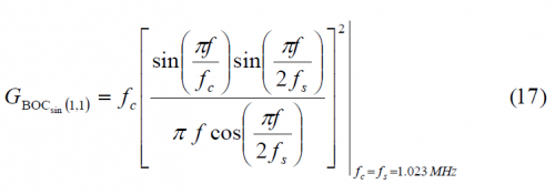
As derived in Power Spectral Density of Sine-phased BOC signals the power spectral density of BOC(1,1) is shown to be:
Nevertheless, since we are interested in finding a simplified expression for the CBCS Power Spectral Density, it is convenient to express BOC(1,1) as a BCS sequence with a vector of length 10. Indeed, BOC(1,1) can also be expressed as BCS([+1,+1,+1,+1,+1,-1,-1,-1,-1,-1],1).
Another way of describing CBCS in the frequency domain is to realize that the BCS signal can be expressed as the sum of a BOC(5,1) signal and an MCS(0,0,0,0,0,0,0,0,0,2) signal in the time domain. Thus, we have to calculate first the Fourier Transform of both, sum them up and calculate the modulus according to equation:
As we know, the spectrum of BOC(5,1) is shown to be:
Equally, the spectrum of a pulse signal of duration [math]\displaystyle{ \left ( T_c / 10 \right ) }[/math] with the pulse centred on the last subchip can be expressed as follows:
Hence the PSDs for the data and pilot signals yields:
CBCS Positioning Performance
One of the performance figures used to select the CBCS signal was the multipath error. In order to realistically estimate the multipath that the candidate signals could present in real environments, the methodology presented in [G.W. Hein and J.-A. Avila-Rodriguez, 2005] [6] and [M. Irsigler et al., 2005] [7] was followed. Furthermore, in order to reduce the computations and given the enormous number of potential signals to assess, a simplified model was employed. Nevertheless, [M. Irsigler et al., 2005] [7] and [M. Irsigler, 2008] [8] have shown that more simplified models also give satisfactory results in the same direction at the expense of generalizing the assumptions and simplifying scenarios.
Another important aspect to note with regards to the CBCS modulation is that the data and pilot channels are in anti-phase and present thus different correlation functions as shown in Power Spectral Density of the CBCS Modulation. The direct consequence of that is that the data and pilot channels present different performance depending on whether the signal has the BOC(1,1) and BCS in phase or in anti-phase. As we will show in the next pages, the anti-phase signal has got the sharpest ACF and thus better performance. For this reason, this was assigned to the pilot channel.
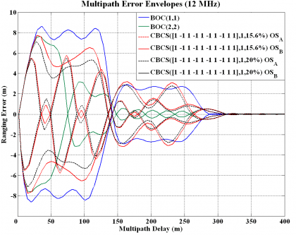
In the following lines we show the performance of CBCS in terms of multipath using the multipath error envelopes. As we know, its computation relies on the assumptions that the line of sight is always visible, that only one multipath signal is present and that the multipath signal experiences a fixed amplitude attenuation (e.g. coefficient of reflection [math]\displaystyle{ \alpha = 0.5 }[/math] in our simulations) with respect to the direct signal. In addition, a static environment is commonly assumed.
More sophisticate models to quantify the differences between the multipath performance of different signals for a given receiver architecture or different receiver implementations have been analyzed in [M. Irsigler, 2008] [8].
In the next figures we compare the performance of the CBCS(20) signal with that of other solutions that were also considered in the past. As we can see, the same CBCS with a slight lower power was also object of the analysis. The reason to reduce the power on the BCS component to 15.6 % was to improve the coexistence of the signal with the rest of signals in the E1/L1 band. Of course, this reduction of power on the BCS part implied a slight deterioration of the performance. Note also that the A and B channels perform the same and thus the dotted and continues curves overlap each other.
As analyses have shown, CBCS presented a considerable improvement of more than 25 % with respect to the baseline for a bandwidth of 24 MHz. Furthermore, the improvement was of even 40 % in terms of multipath with 12 MHz as previous figure shows. This was especially relevant in urban and suburban environments. Moreover, for 12 MHz CBCS performed even better than BOC(2,2). This is a direct consequence of the fact that while BOC(1,1) needs a larger bandwidth of 24 MHz to exploit to the limit the possibilities of the modulation, the CBCS modulation needs a lower bandwidth to make an optimum use of the signal in the sense that its Gabor bandwidth for the same receiver bandwidth is higher. A complete analysis of positioning accuracy using the concept of the User Equivalent Range Error (UERE) was presented by [J.-A. Avila-Rodriguez et al., 2005b] [9] where the superiority of CBCS in different baseline scenarios was demonstrated.
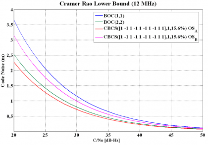
Finally, to have a complete insight into the performance of CBCS, the Cramér Rao Lower Bound (CRLB) is shown in the following figure.
The Cramér Rao Lower Bound is defined in (23) and is the lower bound of the mean-squared error for any estimate of a non-random parameter as shown by [H. Cramér, 1946][10] and [J.-A. Avila-Rodriguez et al., 2006b] [9]. The Cramér-Rao lower bound defines the ultimate accuracy of any estimation and shows the minimum code pseudorange variance we would have with the best possible receiver implementation. Indeed, this bound is a different way of expressing the Gabor bandwidth which sets the physical limit of a signal for a given bandwidth. This last one is also known in the literature as the Root Mean Square (RMS) bandwidth. As shown in Cramér Rao Lower Bound the CRLB is defined as:
where [math]\displaystyle{ B_L }[/math] refers to the loop bandwidth of the code tracking loop and [math]\displaystyle{ R”_{ss}\left ( 0 \right ) }[/math] and [math]\displaystyle{ G_s \left ( f \right ) }[/math] are respectively the autocorrelation and power spectral density of the signal.
The Cramér-Rao lower bound is usually employed to assess the performance of the position estimation based on the delay between the transmitting satellite and the receiver. However, since the function that maps the signal delay to the physical location is not necessarily continuous and differentiable everywhere due to the usual oscillations and discontinuities of the received signal, the Cramér Rao lower bound cannot be applied in all cases. In fact, differentiability is a requirement for the Cramér Rao lower bound to be properly used. As shown in [H. Koorapaty, 2004][11], it may be feasible to create a continuous approximation of this mapping function although this is discontinuous in reality. However, in order to be accurate, the function would need to have large local variations and the Cramér-Rao bound would then be too inaccurate. In the same manner, if a smooth function without large variations were assumed, the bound would also be inaccurate. In particular, such an approach would be too pessimistic in its performance estimates.
As an alternative, the Barankin bound was proposed in [E. Barankin, 1949][12]. As shown in[H. Koorapaty, 2004] [11], the Barankin bound does not require the mapping function to be continuous and differentiable being hence better suited for some problems. The Barankin bound is computed by selecting a set of test points [math]\displaystyle{ [x_1,x_2,\cdots,x_N] }[/math] in the area of analysis and defining the following function:
where [math]\displaystyle{ P \left (r \big | x \right ) }[/math] denotes the conditional probability density function at the set of chosen test points with [math]\displaystyle{ i \in \left \{1,2,\cdots,N \right \} }[/math]. According to this, the Barankin matrix is defined as follows:
with [math]\displaystyle{ \left (i,j \right ) \in \left \{1,2,\cdots,N \right \} \times \left \{1,2,\cdots,N \right \} }[/math]. Furthermore, the Barankin bound on the covariance [math]\displaystyle{ Cov[\hat{x}\left(r\right)] }[/math] for the parameter x based on the measurements r is given by:
where
As we can recognize, the computation of the Barankin bound only requires knowledge of the conditional probability density function [math]\displaystyle{ P \left (r \big | x \right ) }[/math] at the set of chosen test points and no assumption on the differentiability is required. Moreover, it is important to note that the Barankin bound is a lower bound on the covariance matrix of the position errors but it does not say anything about the probability density function of the position errors.
Finally, we must underline that the Barankin bound is more accurate than the Cramér Rao lower bound as shown in [R. McAulay and E. Hofstetter, 1971][13]. In fact, the Barankin bound can be made tighter than the Cramér-Rao bound provided the correct test points are chosen. Moreover, the Barankin bound can be applied in general to more cases than the Cramér Rao bound under the assumption that we have some a priori knowledge on the conditional probability of some particular points. As one can imagine, this information is not always available and justifies the common use of the Cramér Rao lower bound instead.
CBCS Interference Performance
Another important aspect in the performance of a signal is the interference that the signal suffers and causes from and to the rest of signals in the band. The Spectral Separation Coefficient (SSC), to which we will dedicate the next two chapters, is the key figure to assess the isolation among signals and gives us thus a good insight into this problem. In the next tables different SSCs are given for the case that no filter is used at the satellite. However, it must be noted that in case of filtering the spectral isolation would even improve. For the calculations a transmission bandwidth of 40.92 MHz and a receiver bandwidth of 24.00 MHz were assumed.
The self SSC (SSC of one signal with itself) tells us how the intra-system interference is. From the table above we can also recognize that CBCS has better spectral isolation with itself than BOC(1,1) given its wider spreading. Moreover, the CBCS modulation has better spectral isolation with the GPS C/A Code than BOC(1,1) which is logical since part of the power has been moved to higher frequencies. As a conclusion, CBCS presented an improvement in the SSC values that lead to an increase of the minimum C/N0 value (in both Galileo OS and GPS L1C) of up to 0.6 dB, resulting thus in an overall superior link budget.
The interference that we have analyzed so far refers to interference from other GNSS sources. Now we concentrate on the case of non-intentional interference coming from other potential sources. We distinguish between narrowband interference and wideband interference.
- Narrowband interference: The susceptibility to narrow band interference depends on the continuous PSD and on the code structure. Since this latter is not modified by CBCS, and because the continuous PSD of CBCS was wider than that of BOC(1,1), the optimized CBCS presented a higher robustness to narrowband interference.
- Wideband interference: The susceptibility to wide band interference is closely linked to the spreading of the PSD: the more the PSD is spread, the higher the robustness will be. Because CBCS features a PSD which is more spread than that of the BOC(1,1) signal, the CBCS was consequently present a higher robustness than BOC(1,1).
For more details on the mathematical model behind, refer to Power Spectral Density of the CBCS Modulation. As we will see, also here CBCS was superior to BOC(1,1).
One final aspect to analyze the performance of a signal is the acquisition. A very straightforward strategy to acquire CBCS was presented in [G.W. Hein et al., 2005] [1], proving that false acquisition should not represent a big problem. In fact, the only degradation observable with respect to BOC(1,1) would be of less than 1 dB, coming from the correlation losses due to processing with a pure BOC(1,1) receiver.
Receiver Options for CBCS
As presented in [G.W. Hein et al., 2005] [1] and [A.R. Pratt et al., 2006][14] there are several options to receive the CBCS signals. As we will see, some solutions are more efficient while others aim at reducing the receiver complexity as much as possible. We enumerate them next:
- The most straightforward approach is to use a CBCS replica at receiver level for both the data and the pilot channels. As usual, the pilot signal can be used to support data demodulation of the other signal and help in scenarios with poor [math]\displaystyle{ C/N_0 }[/math] ratios.
- A simplified model would be to use a BOC(1,1) replica only. Indeed, as we have repeatedly commented in different parts of this thesis, special care was put during the optimization of the E1 OS signals to achieve a modulation that should be as highly interoperable as possible with BOC(1,1). This option results in a slight loss of signal power (-0.97 dB) but the receiver is then enormously simplified.
- Another imaginable configuration would be to only process the BCS channel extracting thus the difference data message. However, the BCS signal was not optimized for this application, more due to the high data rate than to the low amount of power that was put on the BCS modulation, which was about -6.97 dB lower. Nevertheless, there could be other interesting benefits in terms of improved performance to multipath given the wider bandwidth BCS.
- Another possibility would be to form composite codes from the sum and the difference of the data and pilot codes. By doing so, we could dispread the BOC(1,1) and BCS channels with the BOC(1,1) and BCS signal waveforms correspondingly. This option could also support data-aiding as identified in [A.R. Pratt and J.I.R. Owen, 2005][15] but it would not be absolutely necessary.
Drawbacks of the CBCS solution
After describing all the positive aspects of the CBCS modulation, it is time to describe now the two main drawbacks of CBCS with respect to other solutions that were not selected at that time. These are basically the cross-correlation bias and the need of filtering to achieve spectral compatibility with the rest of signals in the band. We concentrate on them now:
CBCS Cross-Correlation Bias
The selected CBCS solution presented a non-symmetric correlation function when a BOC(1,1) receiver correlates with the incoming CBCS signal as we saw in Figures 4 and 5. As a result, a constant bias appears that is a function only of the percentage of power put on the BCS signal with respect to the OS signal, the received power of the desired signal and the receiver bandwidth. In principle this bias could be corrected if manufacturers would calibrate it as another bias in the receiver processing. Additionally, this bias could be avoided with an appropriate correlation at the receiver [A.R. Pratt et al., 2006][14] and future receivers could consider it as a variable that could be updated at any moment in case future changes in the signal structure would occur. Nevertheless if due to imperfections not all the satellites would be similar, this would introduce a non-negligible complexity that handicapped CBCS.
Different solutions were proposed to avoid the tracking bias, being one of the more interesting the so-called flipping CBCS or CBCS*. This consisted of a BOC(1,1) plus a BCS sequence that alternates its sign from chip to chip. The CBCS* signal would adopt the following form:
where we can recognize that compared to (2) the alternating term [math]\displaystyle{ \left(-1\right)^m }[/math] was introduced to account for the alternation of the BCS sequence from one chip to the other chip. As a result, the cross-correlation between CBCS* and BOC(1,1) would be in average zero as desired. The disadvantage of this approach would be on the other hand that the real length of the BCS would duplicate to all effects due to the phase-alternation.
CBCS Satellite Transmission Filter
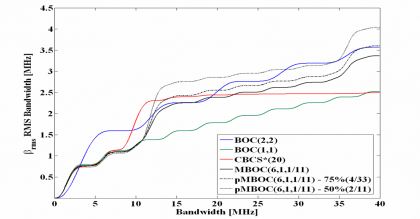
A second and actually the major drawback of the CBCS solution was the need to introduce a filter in the satellite to get sufficient isolation of the third harmonic of the BCS signal with the Galileo PRS signal. As we mentioned above, the selected BCS sequence is qualitatively very similar to a BOC(5,1) which, as we know from theory, has got harmonics at odd multiples of the sub-carrier frequency of 5 MHz. Thus, the third harmonic would fall directly on the PRS at 15 MHz. As suggested in [G.W. Hein et al., 2005] [1] different measures might have been implemented in the satellite payload without inducing a loss of power at user level. A careful selection of the technique guarantees that the main power stays more or less around 5 MHz offset from the centre frequency so that the resulting waveform does not show any significant impact in the multipath error considerations and subsequent performance of the final signal. Whilst this is true, it is also true that from the moment a filter would have been introduced, the multipath mitigation performance would have been limited saturating for wider bandwidths what was a very undesirable property. Similar arguments have also been used against SRRC signals as we will show at the end of this chapter. This can be shown by means of the Root Mean Square bandwidth in the next figure. For completeness also MBOC is depicted. This modulation (baseline of the Galileo Open Service and GPS Civil signals in E1/L1) will be described in detail in the next chapter.
As we know, the Root Mean Square (RMS) bandwidth of a spreading symbol is defined by:
Where [math]\displaystyle{ \bar{G}\left(f\right) }[/math] is normalized for unit power over the signal bandwidth being used, and [math]\displaystyle{ \beta_r }[/math] is the double-sided receiver pre-correlation bandwidth. The RMS bandwidth can also be seen as another way of interpreting the Cramér Rao lower bound or as the Gabor bandwidth of a signal. According to this, the higher the RMS bandwidth, the better the signal will be.
If we observe now the results of Figure 13 above, we can clearly see that unlike CBCS*, the potential RMS bandwidth of MBOC does not saturate for higher bandwidths. CBCS* is the phase alternating version of CBCS that we describe in the following lines. Furthermore, not only is MBOC by far better than BOC(1,1), but it presents also a performance comparable to that of BOC(2,2) and even superior for some implementations. It is interesting to note that for bandwidths higher than about 14 MHz the RMS bandwidth of CBCS* does not grow any more due to the necessary filtering, while that of MBOC does.
As a conclusion, the CBCS signal candidate presented in [G.W. Hein et al., 2005][1] clearly outperformed the baseline BOC(1,1) but presented some inherent limitations that rose some doubts. Especially the two drawbacks explained above were reason of concern since they demanded modification from the receiver manufacturers to get rid of these potential biases. The solution to all those problems would not take much time to come: the name was MBOC and this time, not only Galileo was eager to adopt it, but also GPS for its modernized GPS.
References
- ^ a b c d e f g h i j [G.W. Hein et al., 2005] G.W. Hein, J.-A. Avila-Rodriguez, L. Ries, L. Lestarquit, J.-L. Issler, J. Godet, A.R. Pratt, Members of the Galileo Signal Task Force of the European Commission: A Candidate for the Galileo L1 OS Optimized Signal, Proceedings of the International Technical Meeting of the Institute of Navigation, ION-GNSS 2005, 13-16 September, 2005, Long Beach, California, USA.
- ^ [CNES, 2005] Signaux BOC Multiplexage Temporel pseudo-aleatoire - Analyse de nouvelles formes d'onde et modulation pour les signaux Ouverts Galileo - CNES Technical Note DCT/RF/TT - 2005.139.
- ^ [L. Ries et al., 2006] L. Ries, J.-L. Issler, L. Lestarquit, J.-A. Avila-Rodriguez and G.W. Hein, Spread Spectrum Signal, Patent number WO/2006/075018, International Application No.: PCT/EP2006/050179, Publication date: 20 July 2006
- ^ [P.G. Mattos, 2005] P.G. Mattos, Acquisition of the Galileo OAS L1 b/c Signal for the Mass-Market Receiver, Proceedings of the International Technical Meeting of the Institute of Navigation, ION-GNSS 2005, 13-16 September, 2005, Long Beach, California, USA.
- ^ [F. Soualle et al., 2005] F. Soualle, M. Soellner, S. Wallner, J.-A. Avila-Rodriguez, G.W. Hein, B. Barnes, A.R. Pratt, L. Ries, J. Winkel, C. Lemenager, P. Erhard: Spreading code selection criteria for the future GNSS Galileo, Proceedings of the European Navigation Conference GNSS 2005, 19 - 22 July 2005, Munich, Germany.
- ^ [G.W. Hein and J.-A. Avila-Rodriguez, 2005] G.W. Hein and J.-A. Avila-Rodriguez, Performance of a Galileo PRS/GPS M-Code Combined Service, Proceedings of the National Technical Meeting of the Institute of Navigation, ION-NTM 2005, January 24-26, 2005 , San Diego, California, USA.
- ^ a b [M. Irsigler et al., 2005] M. Irsigler, J.-A. Avila-Rodriguez, G.W. Hein, Criteria for GNSS Multipath Performance Assessment, Proceedings of the 18th International Technical Meeting of the Satellite Division of the Institute of Navigation, ION-GNSS 2005, 13-16 September, 2005, Long Beach, California, USA.
- ^ a b [M. Irsigler, 2008] M. Irsigler, Multipath Propagation, Mitigation and Monitoring in the Light of Galileo and the Modernized GPS, PhD Thesis, University FAF Munich, 2008
- ^ a b [J.-A. Avila-Rodriguez et al., 2005b] J.-A. Avila-Rodriguez, G. W. Hein, S. Wallner, T. Schueler, E. Schueler and M. Irsigler, Revised Combined Galileo/GPS Frequency and Signal Performance Analysis, Proceedings of the International Technical Meeting of the Institute of Navigation, ION-GNSS 2005, 13-16 September, 2005, Long Beach, California, USA.
- ^ [H. Cramér, 1946] H. Cramér. Mathematical Methods of Statistics. Princeton, NJ: Princeton University Press.
- ^ a b [H. Koorapaty, 2004] H. Koorapaty, Barankin bounds for position estimation using received signal strength measurements, in Proceedings of the 59th IEEE Vehicular Technology Conference (VTC '04), vol. 5, pp. 2686-2690, Milan, Italy, May 2004.
- ^ [E. Barankin, 1949] E. Barankin, Locally Best Unbiased Estimates, Annals of Mathematical Stastistics vol. 20, pp. 477-501. 1949.
- ^ [R. McAulay and E. Hofstetter, 1971] R. McAulay and E. Hofstetter, Barankin Bounds on Parameter Estimation, IEEE Transactions on Information Theory, vol. IT-17, number 6, pp. 669-676, 1971.
- ^ a b [A.R. Pratt et al., 2006] A.R. Pratt, J.I.R. Owen, G.W. Hein, J.-A. Avila-Rodriguez: Tracking Complex Modulation Waveforms- How to Avoid Receiver Bias, Proceedings of the International Technical Meeting of the Institute of Navigation, IEEE/ION PLANS 2006, 24-27 April, 2006, Loews Coronado Bay Resort, San Diego, California, USA.
- ^ [A.R. Pratt and J.I.R. Owen, 2005] A.R. Pratt and J.I.R. Owen, Signal Multiplex Techniques in Satellite Channel Availability - Possible Applications to Galileo, Proceedings of the International Technical Meeting of the Institute of Navigation, ION-GNSS 2005, 13-16 September 2005, Long Beach, California, USA.
Credits
The information presented in this NAVIPEDIA’s article is an extract of the PhD work performed by Dr. Jose Ángel Ávila Rodríguez in the FAF University of Munich as part of his Doctoral Thesis “On Generalized Signal Waveforms for Satellite Navigation” presented in June 2008, Munich (Germany)

