If you wish to contribute or participate in the discussions about articles you are invited to contact the Editor
Power Spectral Density of the CBCS Modulation
| Fundamentals | |
|---|---|
| Title | Power Spectral Density of the CBCS Modulation |
| Author(s) | J.A Ávila Rodríguez, University FAF Munich, Germany. |
| Level | Advanced |
| Year of Publication | 2011 |
CBCS is a specific implementation of the MBOC Modulation which receives for this particular case the name of [Composite BOC (CBOC)]]. Thus, all the derivations of this chapter also apply for the CBOC implementation of MBOC that Galileo has selected for the E1 Open Service (OS).
The Composite Binary Coded Symbols modulation, or CBCS for short, is defined as the superposition of a BOC signal with a BCS by means of a modified and optimized Interplex scheme. This last sentence is of great importance because while CBCS specifies the way the signals are multiplexed at payload level, MBOC is more generic and does not say anything about how the time stream should look like.
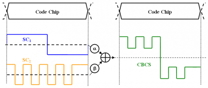
In the most general case, [math]\displaystyle{ CBCS \left( [s],f_c,\rho \right) }[/math] represents the superposition of a [math]\displaystyle{ BOC\left(f_c,f_c\right) }[/math] with a [math]\displaystyle{ BCS\left( [s],f_c,\right) }[/math] in such a way that the BCS component has a percentage [math]\displaystyle{ \rho }[/math] of power with respect to the total power of the multiplexed signal. Furthermore, the vector [s] indicates the symbols that constitute the subchips of the BCS signal. Next figure depicts schematically the principle:
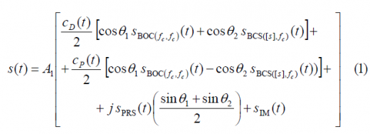
Unlike BPSK, BOC or BCS, the CBCS signal is formed by 4-level sub-carriers. The mathematical definition of CBCS in the time domain:
where,
- [math]\displaystyle{ A_1 }[/math] is the amplitude of the modulation envelope, sum of the OS data and pilot signals, PRS and the Inter-Modulation product IM,
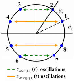
- [math]\displaystyle{ \theta_1 }[/math] and [math]\displaystyle{ \theta_2 }[/math] describe the angular distance between the points of the 8-PSK modulation as depicted in Figure 2,
- [math]\displaystyle{ S_{BOC\left(f_c,f_c\right)}\left(t\right) }[/math] represents the BOC(1,1) modulation with a chip rate [math]\displaystyle{ f_c }[/math],
- [math]\displaystyle{ S_{BCS\left([s],f_c\right)}\left(t\right) }[/math]represents the BCS([s],1) modulation with subchips vector given by [s] and chip rate [math]\displaystyle{ f_c }[/math],
- [math]\displaystyle{ S_{PRS}\left(t\right) }[/math] is the PRS modulation [math]\displaystyle{ BOC_{cos}\left(15,2.5\right) }[/math],
- [math]\displaystyle{ S_{IM}\left(t\right) }[/math] is the Inter-Modulation product signal, and
- [math]\displaystyle{ S_D\left(t\right) }[/math] and [math]\displaystyle{ S_p\left(t\right) }[/math] are the PRN codes for the data and pilot channel of the OS.
The equation above is graphically shown in the figure below. We can recognize that compared with the BOC(1,1) Interplex baseline, two new phase states have appeared to account for the new BCS modulation waveform. Moreover, the quadrature component, namely PRS in the case of Galileo, presents a PSD that is not affected by the waveforms transmitted on the in-phase component.
It is also of interest to note that thanks to the introduction of the additional BCS, there will always be OS signal being emitted at any time for any combination of code chips. This makes the modulation more efficient and reduces the IM power consequently.
Let us now look at the data and pilot channels of the Open Service in detail. In fact, recalling the CBCS time definition, we can easily separate the data and pilot channels as follows:
The autocorrelation of a signal that is stationary in wide sense adopts the following form:
According to this, the autocorrelation function of the data channel can be expressed as
Where [math]\displaystyle{ p_{T_c}^{BOC\left(f_c,f_c\right)} }[/math] and [math]\displaystyle{ p_{T_c}^{BCS\left([s],f_c\right)} }[/math] represent the chip waveforms of [math]\displaystyle{ BOC\left(f_c,f_c\right) }[/math] and [math]\displaystyle{ BCS\left([s],f_c\right) }[/math] correspondingly. This formulation can be further developed if the expectation operator is expressed in integral form as shown next:
or equivalently:
If we further assume that the data codes show ideal properties, then [math]\displaystyle{ \mathfrak{R}_{C_D}\left(m\right)=\delta \left(m\right) }[/math] and the autocorrelation of the data channel yields then:
We can repeat now the same steps for the pilot channel and arrive to a similar expression for the pilot autocorrelation:
Comparing the autocorrelation of the pilot OS with that of the data channel, we can recognize that there is only a sign difference in the cross-correlation term, which is in phase for the data channel and in anti-phase for the pilot channel. Now that we have derived the expressions for the data and pilot autocorrelations of the Open Service, the Power Spectral Densities of both channels can be obtained in the following form:
which can be simplified as shown next:
or equivalently:
According to this, the power of the data channel will be
where, the cross-correlation between [math]\displaystyle{ BOC\left(f_c,f_c\right) }[/math] and [math]\displaystyle{ BCS\left([s],f_c\right) }[/math] is defined as follows:
If we solve now for the pilot channel, it can be shown that the power spectral density of the pilot OS will be:
or expressed in terms of the power spectral density,
such that
If we sum up now the power spectral densities of the data and pilot channels as given by (12) and (16), we obtain the general power expression for the power of the composite OS:
Thus, the total power of the OS signal, with data and pilot together, will be:
adopting the normalized expression of the OS power spectral density the following form:
Since the phase states are sitting on the circle and the power spectral densities of the data and pilot channels are normalized to infinite bandwidth, we can express the normalized power spectral density of the OS signal as follows:
If we have a close look at the expression above, we can see that we can express the percentage of power that falls on the BCS signal as follows:
Thus,
This means, that the total OS power spectral density can be defined as the linear combination of the PSDs of the two waveforms composing the CBCS signal, namely [math]\displaystyle{ BOC\left(f_c,f_c\right) }[/math] and [math]\displaystyle{ BCS\left([s],f_c\right) }[/math], weighted by the percentage [math]\displaystyle{ \rho }[/math] of power that is put on the BCS component.
If we divide now the expressions of the data and pilot power spectral densities given in (12) and (16) by the integrated data and pilot power, we obtain the normalized expressions:
where r indicates the correlation between [math]\displaystyle{ BOC\left(f_c,f_c\right) }[/math] and [math]\displaystyle{ BCS\left([s],f_c\right) }[/math] for zero offset. Equally, for the pilot channel we would have:
Another expression of interest is the power spectral density of the data and pilot channels with respect to the total OS power. Equally interesting is also to obtain the power of the [math]\displaystyle{ BOC\left(f_c,f_c\right) }[/math] and [math]\displaystyle{ BCS\left([s],f_c\right) }[/math] component with respect to the total OS power. We derive next the corresponding expressions.
Let us study first the power of the data channel with respect to the total OS channel. Indeed, if we divide (13) by (18), we obtain the next relationship:
Equally, the percentage of pilot OS power with respect to the total OS power is:
To calculate the total power on the [math]\displaystyle{ BOC\left(f_c,f_c\right) }[/math] signal, we can use the equation (1) and thus,
so that the percentage of [math]\displaystyle{ BOC\left(f_c,f_c\right) }[/math] power with respect to the total OS power will adopt the following form:
If we repeat now for the BCS component,
and normalizing (30) to the total OS power, we have the percentage [math]\displaystyle{ \rho }[/math] of power on the BCS component:
In the same manner, the useful power of the PRS for the quadrature signal can be easily obtained from the signal definition shown at the beginning of this article. In fact:
Equally, for the Inter-Modulation Product we can derive a similar expression:
Finally, if we sum up the power of all the desired signals plus the Inter-Modulation term, we find as expected that the CBCS modulation has constant envelope of amplitude [math]\displaystyle{ A_1 }[/math]:
It is interesting to note that while for the [math]\displaystyle{ BOC\left(f_c,f_c\right) }[/math] Interplex the inter-modulation power only depends on one modulation index, namely m, in the case of CBCS both indexes [math]\displaystyle{ \theta_1 }[/math] and [math]\displaystyle{ \theta_2 }[/math] have to be considered. This means in other words that fixing the IM power is easier with CBCS than it would be if only a [math]\displaystyle{ BOC\left(f_c,f_c\right) }[/math] were transmitted. The result is thus a more efficient control of the IM power since we have more degrees of freedom to play.
One final but important comment is that Interplex with only [math]\displaystyle{ BOC\left(f_c,f_c\right) }[/math] can be easily described taking [math]\displaystyle{ \theta_2 }[/math] equal to π/2.
Once the most important equations describing CBCS have been derived, we study next how to calculate the multiplex parameters when we fix the percentage of power on the BCS component, the power split between data and pilot and the power split between the different signals. Moreover, it is important to note that the expressions derived above were obtained for infinite bandwidth differing thus the results slightly when filtering effects are considered.
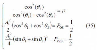
According to the [Galileo SIS ICD, 2008][1] the power split between the OS data and pilot signals shall be 50/50 while the open signals and PRS should have the same power levels. The resulting equations system to solve is then:
where the first equation indicates the amount of power that is moved from [math]\displaystyle{ BOC\left(f_c,f_c\right) }[/math] to the BCS signal and the second and third equations represent the power ratios between the different signals. We can also observe that the equations above do not depend on the specific BCS vector [s] since they only account for power relationships. Nonetheless, as it could be expected, the real BCS vector plays indirectly an outstanding role in assessing if one signal is compatible with the rest of signals in the band or not. In fact, depending on how the specific BCS sequence looks like, the spectral overlapping with the other signals around will be different, determining thus the maximum amount of power [math]\displaystyle{ \rho }[/math] that can be put on its BCS part in order not to interfere.
Until now we have analyzed the case when the BCS signal is on both the data and pilot channels as this is the baseline of Galileo for the OS. Nevertheless, for some specific applications, allocating the high frequency components (thus the BCS signal) only on the pilot channel could be of interest. Indeed, the GPS implementation of MBOC, namely TMBOC, goes in this direction.
In order to have all the power of the BCS signal only on the pilot channel and still maintain constant envelope, the expression of the CBCS modulation has to be generalized. Accordingly, (1) and (2) can be slightly modified as shown next:
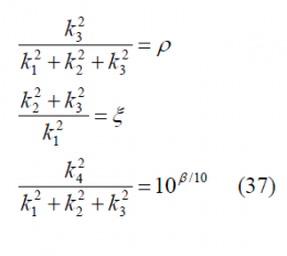
where the constants [math]\displaystyle{ k_1 }[/math],[math]\displaystyle{ k_2 }[/math],[math]\displaystyle{ k_3 }[/math] and [math]\displaystyle{ k_4 }[/math] are calculated from
- the power split between data and pilot,
- the relationship of powers between OS and PRS,
- the percentage of power on the BCS signal with respect to the total OS power under the constraint that the phase points are on the unit circle, and
- accounting for the different filter losses of the signals due to bandlimiting.
Mathematically, all these conditions can be expressed as follows
where:
- [math]\displaystyle{ \rho }[/math] is the percentage of power on the BCS signal,
- [math]\displaystyle{ \xi }[/math] indicates the percentage of power that falls onto the pilot channel with respect to the data channel. Thus, if we have a power split of 50/50, [math]\displaystyle{ \xi = 1 }[/math] and for 75/25, [math]\displaystyle{ \xi = 3 }[/math],
- and [math]\displaystyle{ \beta }[/math] indicates the power difference between PRS and OS in dB, accounting for the different filter losses of both signals due to satellite bandlimiting.
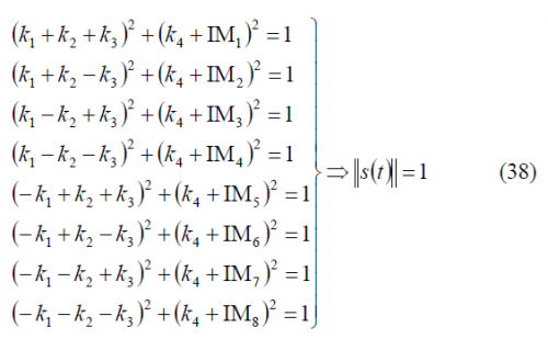
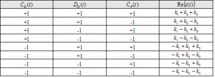
It should be noted that this calculation ignores the effect of the correlation between the [math]\displaystyle{ BOC\left(f_c,f_c\right) }[/math] and [math]\displaystyle{ BCS\left([s],f_c\right) }[/math], which is introduced by virtue of the satellite bandlimiting. Additionally, since all the phase points have to be on the unit circle, we have:
since the real component of the signal takes 8 values with equal probability, given as shown in the following table:
Additionally, the IM component [math]\displaystyle{ IM=\left \{IM_1,IM_2,\cdots,IM_8 \right \} }[/math] must take the appropriate value to bring the phase plots to the unit circle. Note that this is true independently of the BCS component is in phase or in anti-phase. Finally, an extra constraint comes from the necessary condition that the Inter-Modulation signal has zero mean:
If we put all the conditions together, we can see that we have totally twelve equations, namely (37), (38) and (39), and twelve unknowns to find, namely , [math]\displaystyle{ k_1 }[/math],[math]\displaystyle{ k_2 }[/math],[math]\displaystyle{ k_3 }[/math] and [math]\displaystyle{ k_4 }[/math]. Unfortunately, while (36) covers more cases than (1) and (2), in general it is not possible to find an explicit expression for the coefficients [math]\displaystyle{ k_1 }[/math],[math]\displaystyle{ k_2 }[/math],[math]\displaystyle{ k_3 }[/math] and [math]\displaystyle{ k_4 }[/math].
We show next with an example how the parameters of the CBCS multiplex could be obtained for the hypothetical case that the CBOC implementation of MBOC would allocate the whole BOC(6,1) component on the pilot OS signal. The power ratio between the BCS signal, in this particular case BOC(6,1), and the total OS power is 1/11 at generation. This means that in reality the power after filtering in the satellite will be slightly lower on BOC(6,1). Moreover, let us assume that the PRS power would be 2 dB above the OS power at user level and that the effect of filtering in the satellite is also taken into account. This assumption is different from the baseline when OS and PRS have the same power.
If we solve now for CBOC(6,1,1/11) with all the BOC(6,1) power on the pilot channel, with equal power for pilot and data, with 1/11 of the OS power in the BOC(6,1) before bandlimiting, the composite signal may be defined by
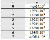
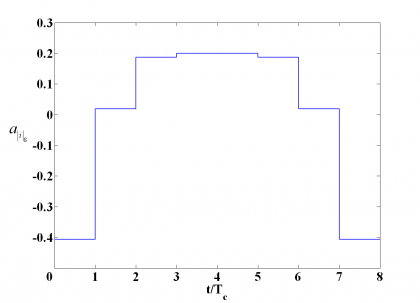
where the signal [math]\displaystyle{ sc_{IM}\left(t\right) }[/math] is given by:
adopting [math]\displaystyle{ a_{\left | I \right \vert _s} }[/math] the following values:
We show the Inter-Modulation signal next graphically:
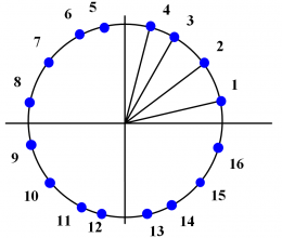
The phase states of the constellation are equally shown in the next figure. As we can see, the main effect is that the number of states has duplicated, what is of course a clear drawback. In addition, it is important to realize that this implementation of CBOC is not compliant with the MBOC spectrum definition since a cross term appears.
References
- ^ [Galileo SIS ICD, 2008] Galileo Open Service Signal In Space Interface Control Document (OS SIS ICD) Draft 1 01/02/2008, 2008, European Space Agency / Galileo Joint Undertaking.
Credits
The information presented in this NAVIPEDIA’s article is an extract of the PhD work performed by Dr. Jose Ángel Ávila Rodríguez in the FAF University of Munich as part of his Doctoral Thesis “On Generalized Signal Waveforms for Satellite Navigation” presented in June 2008, Munich (Germany)

