If you wish to contribute or participate in the discussions about articles you are invited to contact the Editor
Carrier phase ambiguity fixing with three frequencies
| Fundamentals | |
|---|---|
| Title | Carrier phase ambiguity fixing with three frequencies |
| Author(s) | J. Sanz Subirana, J.M. Juan Zornoza and M. Hernández-Pajares, Technical University of Catalonia, Spain. |
| Level | Advanced |
| Year of Publication | 2011 |
With two frequency signals, in RTK or WARTK, the convergence time is linked to the wide-lane ambiguity ([math]\displaystyle{ \Delta \nabla N_W }[/math]) fixing. With three frequency systems, using two close frequency signals, it is possible to generate an extra-wide-lane signal to enable the single epoch wide-lane ambiguity fixing. That is, without needing the time span required by equation (1) to smooth the code noise up to the roundoff threshold (see Carrier phase ambiguity fixing with two frequencies).
- [math]\displaystyle{ \Delta \nabla N_W=\left [\frac{\Delta \nabla \Phi_{_W}-\Delta \nabla R_{_N}}{\lambda_W} \right]_{\mbox{roundoff}} \qquad \mbox{(1)} }[/math]
For a better clearness in the presentation of concepts, the following definitions and notation will be used:
- [math]\displaystyle{ \begin{array}{c} \Phi_{_{EW}}=\Phi_{_{W_{23}}};\qquad \Phi_{_W}=\Phi_{_{W_{12}}};\qquad R_{_{EN}}=R_{_{N_{23}}} \end{array} \qquad \mbox{(2)} }[/math]
where the wide-lanes and narrow-lanes combinations are computed combining the respective frequencies according to the equations (3) and (4) (see Combination of GNSS Measurements )
- [math]\displaystyle{ \Phi_{_{LW}}=\frac{f_1\;\Phi_{_{L1}}-f_2\;\Phi_{_{L2}}}{f_1-f_2}~~~~~;~~~~~ R_{_{PW}}=\frac{f_1\;R_{_{P1}}-f_2\;R_{_{P2}}}{f_1-f_2} \qquad \mbox{(3)} }[/math]
- [math]\displaystyle{ \Phi_{_{LN}}=\frac{f_1\;\Phi_{_{L1}}+f_2\;\Phi_{_{L2}}}{f_1+f_2}~~~~~;~~~~~ R_{_{PN}}=\frac{f_1\;R_{_{P1}}+f_2\;R_{_{P2}}}{f_1+f_2} \qquad \mbox{(4)} }[/math]
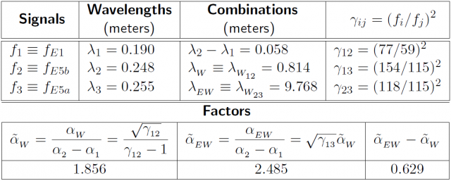
Moreover, the frequencies and values of table 1 will be taken as a reference for the numerical application.
With three frequency signals, the following ambiguity fixing procedure can be considered [footnotes 1]:
- Wide-lane ambiguity fixing:
The equation (1) is replaced by the next two equations (5) and (6)
- Extra-wide-lane ambiguity fixing:
- [math]\displaystyle{ \Delta \nabla N_{EW}=\left [\frac{\Delta \nabla \Phi_{EW}-\Delta \nabla R_{EN}}{\lambda_{EW}} \right ]_{\mbox{roundoff}} \qquad \mbox{(5)} }[/math]
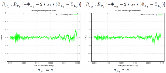
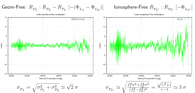
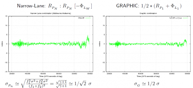
- As it is shown in figure 1 (see GNSS Measurement features and noise), the code noise in the extra-narrow-lane combination [math]\displaystyle{ \Delta \nabla R_{EN} }[/math] is reduced by a factor [footnotes 2] about [math]\displaystyle{ \sqrt{2} }[/math] and, on the other hand, the ambiguity spacing is enlarged by the extra-wide-lane combination. If the frequencies of table 1 are used, thence [math]\displaystyle{ \lambda_{_{EW}}=9.678\,m }[/math], which means about 10 times the [math]\displaystyle{ \lambda_{_{W}} }[/math] and about 50 times the [math]\displaystyle{ \lambda_1 }[/math] ambiguity spacing.
Figure 1: Comparison of code pseudorange noise for the original GPS [math]\displaystyle{ R_{_{P_1}} }[/math] and [math]\displaystyle{ R_{_{P_2}} }[/math] raw code measurements and their main combinations (see captions) The geometry and the dispersive delays have been removed by a combination of carrier phases [indicated within the brackets]. The approximate expression of [math]\displaystyle{ \sigma }[/math]-noise is given above each plot. Note: [math]\displaystyle{ \tilde{\alpha}_1=\frac{1}{\gamma-1} }[/math], [math]\displaystyle{ \tilde{\alpha}_2=\gamma \, \tilde{\alpha}_1 }[/math], and [math]\displaystyle{ \gamma=(77/60)^2\simeq 1.65 }[/math]
- Thence, being the measurement noise far from the rounding threshold, the extra-wide-lane ambiguity ([math]\displaystyle{ \Delta \nabla N_{EW} }[/math]) can be fixed in single epoch.
- Wide-lane ambiguity fixing:
- [math]\displaystyle{ \Delta \nabla N_{W}=\left [\frac{\lambda_{EW} \Delta \nabla N_{EW} +(\tilde{\alpha}_{_{EW}}-\tilde{\alpha}_{_{W}}) \Delta \nabla I - \left (\Delta \nabla \Phi_{EW} - \Delta \nabla \Phi_{W} \right)}{\lambda_{W}} \right ]_{\mbox{roundoff}} \qquad \mbox{(6)} }[/math]
- Using the values of table 1, the coefficient of the ionospheric term [math]\displaystyle{ \Delta \nabla I }[/math] is [math]\displaystyle{ \tilde{\alpha}_{_{EW}}-\tilde{\alpha}_{_{W}}=0.63 }[/math]. This allows an error up to [math]\displaystyle{ 0.65\,cm }[/math] in the [math]\displaystyle{ \Phi_1-\Phi_2 }[/math] delay (or [math]\displaystyle{ 6.5 }[/math] TECUs) for the ionosphere to fit into the rounding threshold (i.e., [math]\displaystyle{ \lambda_{_W}/2 }[/math]). That is, more than 20 times the error threshold allowed by the equation (7) (see Carrier phase ambiguity fixing with two frequencies).
- [math]\displaystyle{ \Delta \nabla N_1= \left [ \frac{\Delta \nabla \Phi_1 - \Delta \nabla \Phi_2 - \Delta \nabla I- \lambda_2 \Delta \nabla N_W}{\lambda_2 -\lambda_1} \right ]_{\mbox{roundoff}} \qquad \mbox{(7)} }[/math]
- Thence, being the [math]\displaystyle{ \Delta \nabla N_{EW} }[/math] ambiguity fixed, the limiting factor in this equation would be the carrier phase multipath. Notice that the carrier phase noise in the extra-wide-lane combination is several times larger than in the original signals. That is [math]\displaystyle{ \sigma_{_{\Phi_{EW}}}\simeq\frac{\sqrt{\gamma_{_{23}}+1}}{\sqrt{\gamma_{_{23}}}-1}\;\sigma\simeq 55\,\sigma }[/math], where [math]\displaystyle{ \sigma\equiv\sigma_{_{\Phi_{E5b}}}\simeq\sigma_{_{\Phi_{E5a}}} }[/math]
- Narrow-lane ambiguity fixing:
As in the two frequency case, once the wide-lane ambiguity is fixed, the narrow-lane ambiguity can be fixed by whatever the equations (7) and (8) (see Carrier phase ambiguity fixing with two frequencies).
- [math]\displaystyle{ \Delta \nabla N_1=\left [\frac{1}{\lambda_N}\left (\Delta \nabla \hat{B}_c \right) - \frac{\lambda_W}{\lambda_2}\Delta \nabla N_W \right]_{\mbox{roundoff}} \qquad \mbox{(8)} }[/math]
After fixing such ambiguities, the unambiguous ionosphere-free bias [math]\displaystyle{ \Delta \nabla B_{C} }[/math] can be obtained by the equation (9) (see Carrier phase ambiguity fixing with two frequencies).
- [math]\displaystyle{ \Delta \nabla B_C=\lambda_N \left (\Delta \nabla N_1+\frac{\lambda_W}{\lambda_2}\Delta \nabla N_W \right) \qquad \mbox{(9)} }[/math]
If single epoch ambiguity fixing is desired, thence the equation (7) must be used to fix [math]\displaystyle{ \Delta \nabla N_1 }[/math]. That is:
- [math]\displaystyle{ \Delta \nabla N_1=\left [\frac{\Delta \nabla \Phi_1 - \Delta \nabla \Phi_2 - \Delta \nabla I- \lambda_2 \Delta \nabla N_W}{\lambda_2 -\lambda_1} \right ]_{\mbox{roundoff}} \qquad \mbox{(10)} }[/math]
Notice that, as in the two frequencies case studied in the previous section, this equation is affected by the ionospheric refraction decorrelation with the distance, limiting the ambiguity fixing to short baselines (as in the TCAR or CIR techniques) if an accurate prediction of [math]\displaystyle{ \Delta \nabla I }[/math] is not available for the user. Thence, the WARTK [Hernandez-Pajares et al., 2000] [1] allows to extend the baselines up to hundreds of kilometres thanks to an accurate modelling of the ionosphere.
 Table 1:Values to illustrate the ambiguity fixing concepts (taken from Tables 1 and 2 of the article Combining pairs of signals and clock definition). Notice that the factors [math]\displaystyle{ \tilde{\alpha}_i }[/math] are normalised regarding to [math]\displaystyle{ \alpha_2-\alpha_1 }[/math], associated to the frequencies [math]\displaystyle{ f_1 }[/math], [math]\displaystyle{ f_2 }[/math] used for the ionosphere-free combination
Notes
- ^ The equations (5) and (6) are derived from the equations (3) and (4) of the article Combination of GNSS Measurements.
- ^ [math]\displaystyle{ \sigma_{_{R_{EN}}}\simeq\frac{\sqrt{\gamma_{23}+1}}{\sqrt{\gamma_{23}}+1}\,\sigma \simeq 1/\sqrt{2}\,\sigma }[/math], where uncorrelated errors are assumed and with the same noise [math]\displaystyle{ \sigma\equiv\sigma_{_{R_{E5b}}}\simeq\sigma_{_{R_{E5a}}} }[/math].
References
- ^ [Hernandez-Pajares et al., 2000] Hernandez-Pajares, M., Juan, J., Sanz, J. and Colombo, O., 2000. Application of ionospheric tomography to real-time GPS carrier-phase ambiguities resolution, at scales of 400-1000 Km and with high ionospheric activity. Geophysical research letters.


