If you wish to contribute or participate in the discussions about articles you are invited to contact the Editor
Ionospheric Delay
| Fundamentals | |
|---|---|
| Title | Ionospheric Delay |
| Author(s) | J. Sanz Subirana, J.M. Juan Zornoza and M. Hernández-Pajares, Technical University of Catalonia, Spain. |
| Level | Advanced |
| Year of Publication | 2011 |
The ionosphere is the zone of the terrestrial atmosphere that extends itself from about 60 km until more than 2.000 km in high. As it name says, it contains a partially ionised medium, as result of the X and UV rays of Solar Radiation and the incidence of charged particles.
The propagation speed of the GNSS electromagnetic signals in the ionosphere depends on its electron density (see below), which is typically driven by two main processes: during the day, sun radiation causes ionisation of neutral atoms producing free electrons and ions. During the night, the recombination process prevails, where free electrons are recombined with ions to produce neutral particles, which leads to a reduction in the electron density.
A medium where the angular frequency [math]\displaystyle{ \omega }[/math] and the wave number [math]\displaystyle{ k }[/math] are not proportional, is a dispersive media (i.e., the wave propagation speed and thence, the refractive index depends on the frequency). This is the case with the ionosphere where [math]\displaystyle{ \omega }[/math] and [math]\displaystyle{ k }[/math] are related, in a first approximation, by [Crawford, 1968][1]:
- [math]\displaystyle{ \omega^2=c^2k^2+\omega_p^2 \qquad \mbox{(1)} }[/math]
where [math]\displaystyle{ c }[/math] is the propagation speed of a signal in the vacuum and [Davies, 1989][2]
- [math]\displaystyle{ \omega_p=2\pi\, f_p \qquad\mbox{with}\qquad f_p=8.98\sqrt{N_e} \qquad\mbox{in Hz} \qquad\mbox{(2)} }[/math]
being [math]\displaystyle{ N_e }[/math] the electron density (in [math]\displaystyle{ e^-/m^3 }[/math]). A complete derivation of this relationship can be found in [Davies, 1989][2]and the updated higher order terms in [McCarthy,D. and Petit,G., 2009][3], typically less than 0.1% of the total delay.
The previous equation (1) is named the Relation of Dispersion of the ionosphere, and [math]\displaystyle{ \omega_p }[/math] is called the critical frequency of the ionospheric plasma, in the sense that signals with [math]\displaystyle{ \omega \lt \omega_p }[/math] will be reflected and signals with [math]\displaystyle{ \omega \gt \omega_p }[/math] will cross through the plasma [Davies, 1989] [4].
The electron density in the ionosphere changes with the height having a maximum of [math]\displaystyle{ N_e\simeq 10^{11} - 10^{12} e^-/m^3 }[/math] around [math]\displaystyle{ 300-500\, km }[/math]. Thence, according to the expression (2), electromagnetic signals with [math]\displaystyle{ f\gt f_p \simeq 10^6Hz }[/math] will be able to cross the ionosphere. This is the case of GNSS signals which frequencies are at the order of 1 GHz = [math]\displaystyle{ 10^9 }[/math] Hz. Radio signals with frequencies under [math]\displaystyle{ f_p }[/math] will be reflected in the ionosphere.
From equation (1), and taking into account that [math]\displaystyle{ \omega=2\pi f }[/math] and the definition of Phase & Group Velocity
- [math]\displaystyle{ v_{ph}=\frac {\omega}{ k}~,\qquad v_{gr}=\frac {d\omega}{d k} \qquad\mbox{(3)} }[/math]
it follows:
- [math]\displaystyle{ v_{ph}= \frac{c}{\sqrt{1-\left(\frac{f_p}{f} \right)^2}} \qquad\mbox{(4)} }[/math]
Thence, according to (5),
- [math]\displaystyle{ n_{ph}=\frac c{v_{ph}} \qquad ~, \qquad n_{gr}=\frac c{v_{gr}} \qquad\mbox{(5)} }[/math]
the phase refractive index of the ionosphere can be approximated[footnotes 1]by:
- [math]\displaystyle{ n_{ph}=\sqrt{1-\left(\frac{f_p}{f} \right)^2}\simeq 1-\frac{1}{2}\left(\frac{f_p}{f} \right)^2= 1-\frac{40.3}{f^2}N_e \qquad\mbox{(6)} }[/math]
At the frequency of GNSS signals, the previous approximation (7) accounts for more than the 99.9% of the refractivity (first order ionospheric effect). That is, with less than a 0.1% of error, it can be assumed:
- [math]\displaystyle{ n_{ph}=1-\frac{40.3}{f^2}N_e \qquad\mbox{(7)} }[/math]
Differentiating the equation (1) with respect to [math]\displaystyle{ k }[/math] and taking into account (3), (5) and the approximation [math]\displaystyle{ (1-\varepsilon^2)^{-1/2}=1+\frac{1}{2} \varepsilon^2 }[/math], yields the group refractive index: [footnotes 2]
- [math]\displaystyle{ n_{gr}=1+\frac{40.3}{f^2}N_e \qquad\mbox{(8)} }[/math]
Substituting the phase and group refraction indices (7) and (8) in
- [math]\displaystyle{ \Delta=\int_{_{\mbox{straight line}}}{(n-1)\,dl} \qquad\mbox{(9)} }[/math]
the difference between the measured range (with the frequency [math]\displaystyle{ f }[/math] signal) and the Euclidean distance between the satellite and receiver is given by:
- [math]\displaystyle{ \Delta_{ph,f}^{iono}=-\displaystyle\frac{40.3}{f^2}\int{N_e\, dl} \qquad \qquad \Delta_{gr,f}^{iono}=+\displaystyle\frac{40.3}{f^2}\int{N_e\, dl} \qquad\mbox{(10)} }[/math]
Thence, phase measurements suffer advancement when crossing the ionosphere, i.e., a negative delay, and the code measurements suffer a positive delay.
The differences [math]\displaystyle{ \Delta_{ph,f}^{iono} }[/math] and [math]\displaystyle{ \Delta_{gr,f}^{iono} }[/math] are called the phase and code ionospheric refraction and, the integral is defined as the Slant TEC (STEC):
- [math]\displaystyle{ STEC=\int{N_e\, dl} \qquad\mbox{(11)} }[/math]
Usually, the [math]\displaystyle{ STEC }[/math] is given in TEC units (TECUs), where [math]\displaystyle{ 1\,TECU=10^{16}e^-/m^2 }[/math] and the ionospheric delay [math]\displaystyle{ I_f }[/math] (at the frequency [math]\displaystyle{ f }[/math]) is written as:
- [math]\displaystyle{ I_f\equiv \Delta_{gr,f}^{iono}= \alpha_f\,STEC \qquad\mbox{(units: meters of delay)} \qquad\mbox{(12)} }[/math]
with
- [math]\displaystyle{ \alpha_f= \frac{40.3\cdot 10^{16}}{f^2}\; m_{\mbox{signal delay}_{(\mbox{at frequency}f)}}/_{TECU} \qquad\mbox{(where f is in Hz)} \qquad\mbox{(13)} }[/math]
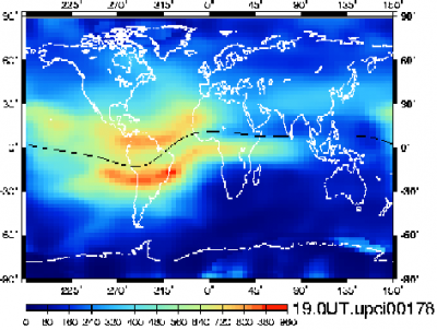
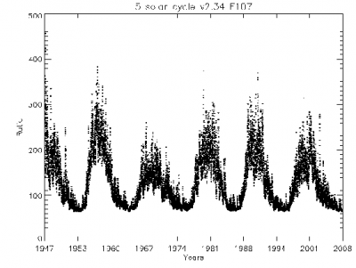
The TEC, and thence, the ionospheric refraction depends on the geographical location of the receiver, the hour of day and the solar activity. Figure 1, left, shows a Vertical TEC map with the geographical distribution of the TEC, where the equatorial anomalies are clearly depicted around the geomagnetic equator. The plot at right shows the [math]\displaystyle{ 11 }[/math] year solar cycle with a Solar flux plot.
Figure 1: Figure at left: Vertical Total Electron Content in units of [math]\displaystyle{ 0.1 }[/math] [math]\displaystyle{ TECUs\simeq 1.6\,cm }[/math] of delay in the GPS L1 signal at 19UT of the 26th of June of 2000. The plot at right shows the Solar flux evolution during the last solar cycles.
As the ionosphere is a dispersive media, the GNSS signals refraction depends on its frequencies (as the squared inverse). This dependence on the signal frequency allows us to remove its effect up to more than 99.9% using two frequency measurements
(see Ionosphere-free Combination for Dual Frequency Receivers). But, single frequency receivers have to apply an ionospheric prediction model to remove (as much as possible) this effect, that can reach up to several teens of meters (see Klobuchar Ionospheric Model and NeQuick Ionospheric Model).
Advanced comment: Second order ionospheric effect
The previous results of equation (12) are many often referred as the First Order Ionospheric effect, being denoted as [math]\displaystyle{ I1_f\equiv I_f }[/math]. That is:
- [math]\displaystyle{ I1_{ph,f}=-\alpha_f STEC=-I1_{gr,f} \qquad\mbox{(14)} }[/math]
As commented before, the equation (1) is a simplification of the Relation of Dispersion of the ionosphere given in [McCarthy,D. and Petit,G., 2009][3], where the dependence of the refraction index with the magnetic field [math]\displaystyle{ {\mathbf B} }[/math] has been neglected. If such terms are taken into account, higher order ionospheric terms appears (but, they mean less than the [math]\displaystyle{ 0.1\% }[/math] of the total effect).
The Second Order Ionospheric term, its implementation and impact on geodetic estimates is analysed in detail in [Hernandez-Pajares et al., 2007][5].Its effect on carrier ([math]\displaystyle{ I2_{ph,f} }[/math]) and code ([math]\displaystyle{ I2_{gr,f} }[/math]) measurements at the frequency [math]\displaystyle{ f }[/math] is given by:
- [math]\displaystyle{ I2_{ph,f}=-\displaystyle \frac{7527\, c}{2 \,f_1^3}\int_{rec}^{sat} N_e B \cos{\theta}\, dl \qquad\mbox{(15)} }[/math]
- [math]\displaystyle{ I2_{gr,f}=-2\;I2_{ph,f} \qquad\mbox{(16)} }[/math]
where [math]\displaystyle{ c }[/math] is the speed of light. [math]\displaystyle{ B }[/math] is the module of the earth magnetic field [math]\displaystyle{ {\mathbf B} }[/math] and [math]\displaystyle{ \theta }[/math] the angle between [math]\displaystyle{ B }[/math] and the propagation direction. The units are in the International System of Units (SI).
In global geodetic computations, [math]\displaystyle{ I2 }[/math] mainly affects to the satellite clocks estimate
(cm level) and orbits (few mm), but the impact on receiver positions is usually smaller than [math]\displaystyle{ 1 }[/math] mm (static positioning).
For more information, see:
Notes
- ^ The approximation [math]\displaystyle{ \sqrt{1-x^2}\simeq 1-\frac{1}{2}x^2 }[/math] can be used when [math]\displaystyle{ |x| \ll 1 }[/math]. Notice that taking [math]\displaystyle{ f=10^9 }[/math] Hz as the frequency of the GNSS signals, and being [math]\displaystyle{ f_p\simeq 10^7 }[/math] Hz, thence, [math]\displaystyle{ x=f_p/f\simeq 10^{-2} }[/math], which justifies the approximation.
- ^ Notice that [math]\displaystyle{ n_{gr}\gt n_{ph} }[/math] and, thus, from (5) it follows that [math]\displaystyle{ v_{gr}\lt v_{ph} }[/math]. Moreover, as [math]\displaystyle{ n_{ph}\lt 1 }[/math], thence [math]\displaystyle{ v_{ph}=\frac{c}{n_{ph}}\gt c }[/math]. That is, the phase travels faster than the speed of light, but no information is carried, so no the relativity principle is violated.
References
- ^ [Crawford, 1968] Crawford, F., 1968. Berkeley Physics Course, Vol. 3 WAVES. Mc Graw-Hill, Inc., New York, USA.
- ^ a b [Davies, 1989] page 94: [math]\displaystyle{ N_e=1.24\cdot 10^{10} f_p^2 }[/math], with [math]\displaystyle{ f_p }[/math] in megahertz and [math]\displaystyle{ N_e }[/math] in electrons per meter cubic.
- ^ a b [McCarthy,D. and Petit,G., 2009] McCarthy,D. and Petit,G., 2009. IERS Conventions (2009) (draft), Chap. 9. ftp://tai.bipm.org/iers/convupdt/chapter9/icc9.pdf.
- ^ [Davies, 1989] Davies, K., 1989. Ionosphere Radio. IEE Electromagnetic Waves Series 31. Peter Peregrinus Ltd., Boulder, Colorado, USA.
- ^ [Hernandez-Pajares et al., 2007] Hernandez-Pajares, M., Juan, J. and Sanz, J.,2007. Second-order ionospheric term in GPS: Implementation and impact on geodetic estimates . Journal of Geophysical Research. 112, pp. 1-16.


