If you wish to contribute or participate in the discussions about articles you are invited to contact the Editor
GNSS Measurements Modelling
| Fundamentals | |
|---|---|
| Title | GNSS Measurements Modelling |
| Author(s) | J. Sanz Subirana, J.M. Juan Zornoza and M. Hernández-Pajares, Technical University of Catalonia, Spain. |
| Level | Basic |
| Year of Publication | 2011 |
The aim of this article is to provide the background for the measurement's modelling for the Standard and Precise Point Positioning. Applying this modelling, the user-receiver would correct each measurement from the known delay.
Introduction
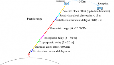
The code and carrier phase measurements contains several additional time delays associated to the signal propagation or to the clocks, among the geometric range between the satellite and receiver (see GNSS basic observables). These delays are common for code and carrier measurements, except for the wind-up and the ambiguities that affect only to the carrier measurements, and for a sign in the ionospheric refraction, delaying the code and advancing the carrier measurements (see Ionospheric Delay).
Figure 1 shows a layout of the diferent time-delays terms in the pseudorange to illustrate the measurements content.
The measurements can be modelled by the following equations:
[math]\displaystyle{ R_{_i}=\rho+c(\delta t_{rcv}-\delta t^{sat})+Tr+\tilde{\alpha_i}(I+K_{21})+\mathcal{M}_i+\varepsilon_i\,\,\,\,\,\,\ (i=1,2) }[/math]
[math]\displaystyle{ \Phi_{_i}=\rho+c(\delta t_{rcv}-\delta t^{sat})+Tr- \tilde{\alpha_i}\, I +b_i+\lambda_i\,N_i+\lambda_i w+m_i+\epsilon_i \qquad \mbox{(1)} }[/math]
where the satellite clock offset [math]\displaystyle{ \delta t^{sat} }[/math] includes the relativistic clock correction and range [math]\displaystyle{ \rho }[/math] the relativistic path correction.
See the equations (1) derivation in the article combination of pairs of signals. Remark: In such equations a term '[math]\displaystyle{ -\tilde{\alpha_i}K_{21} }[/math]' is always added to the carrier measurements to have closed expressions for the combinations of measurements (with the ionosphere always joining the DCBs as '[math]\displaystyle{ I+K_{21} }[/math]'). This term has been assimilated here into the unknown bias ([math]\displaystyle{ b_i+\lambda_i\,N_i }[/math]), for simplicity. Note that, as the carrier measurement contans an unknown bias, it can be redefined without loss of generality to include such DCBs. These closed expressions are specially useful when working with combinations of pairs of frequencies, as in Undifferenced Ambiguity Fixing, to simplify the relationships between equations and parameters.
The residuals between the measured and predicted code or carrier pseudoranges, contain the receiver position error and clock offsets, plus miss-modelling and measurement noise errors. These residuals, that from hereafter will be called prefit-residuals, are the input data for the navigation equations. Such equations consist on a linear system which solution by Least Squares of the Kalman filtering allows to decorrelate (i.e., separate) the different error components from the prefit residuals and, thence, to determine the receiver coordinates. The more accurate measurement modelling is performed, the better decorrelation of errors is achieved and, thence, more accurate coordinates are obtained.
Related Articles
In the following entries, the GNSS measurements modelling is split into their different contributors:

