If you wish to contribute or participate in the discussions about articles you are invited to contact the Editor
NeQuick Ionospheric Model
| Fundamentals | |
|---|---|
| Title | NeQuick Ionospheric Model |
| Author(s) | J. Sanz Subirana, JM. Juan Zornoza and M. Hernandez-Pajares, University of Catalunia, Spain. |
| Level | Intermediate |
| Year of Publication | 2011 |
The NeQuick is the ionospheric model proposed to be used by the Galileo single frequency receiver to compute ionospheric corrections. It is based on the original profiler proposed by [1].
NeQuick is a tridimensional and time-dependent ionospheric electron density model, which provides electron density in the ionosphere as a function of the position and time. Thence, it allows to compute ionospheric delays (TEC or STEC), as the integrated electron density along any ray path.
NeQuick FORTRAN 77 code was accepted by the ITU-R in 2000 and revised in 2002. It is freely available from the ITU. It is referred to either as version 1 or ITU-R. This package, includes a comprehensive description of the implementation as well as numerical integration subroutines allowing to compute Vertical and Slant TEC.
The input parameters of the model are the position (longitude, latitude and height), the epoch (month and UT) and the solar activity (either expressed [footnotes 1] as F10.7 or R12). Other internal parameters are the foF2 and M(3000)F2 values, which can be defined according to the ITU-R, amongst other options depending on the purpose.
The NeQuick model running in the Galileo single frequency receivers will be driven by the Effective Ionisation Level, [math]\displaystyle{ Az }[/math] parameter (replacing the solar flux), that is a function of the receiver location.
- [math]\displaystyle{ Az=a_0+a_1\mu + a_2 \mu^2 \qquad\mbox{(1)} }[/math]
where [math]\displaystyle{ \mu }[/math] is the modified dip latitude, or MODIP:
- [math]\displaystyle{ \tan \mu=\displaystyle \frac{I}{\sqrt{\cos \phi}}\qquad\mbox{(2)} }[/math]
being [math]\displaystyle{ I }[/math] the true magnetic inclination[footnotes 2], or dip in the ionosphere (usually at 300 km), and [math]\displaystyle{ \phi }[/math] the geographic latitude of the receiver [2].
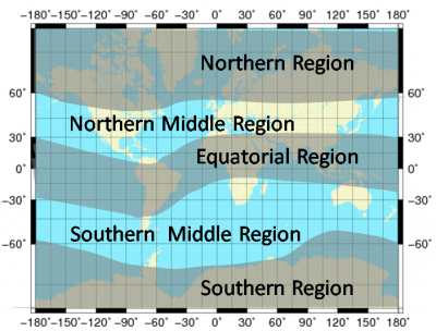
The coefficients [math]\displaystyle{ a_0 }[/math], [math]\displaystyle{ a_1 }[/math],[math]\displaystyle{ a_2 }[/math] will be broadcasted to the users in the Galileo navigation message and updated at least once a day [footnotes 3]. Ionospheric Disturbance Flag alerts for five predefined regions (see Figure 1) will be also broadcasted to aware the users when the ionospheric correction coming from the Galileo broadcast message might not meet the specified performance. These disturbance flags will be transmitted continuously and updated with the update rate of the Navigation Message (every [math]\displaystyle{ 100 }[/math] minutes).
 Figure 1: The 5 Regions defined for the Disturbance Flags (in degrees MODIP) -90 to -60, -60 to -30, -30 to 30, 30-60, 60-90. (courtesy of [3]).
The Galileo single frequency receiver algorithm will be based in the following steps (the next paragraph is taken from [3]):
- 1. [math]\displaystyle{ Az }[/math] is evaluated using [math]\displaystyle{ a_0 }[/math], [math]\displaystyle{ a_1 }[/math],[math]\displaystyle{ a_2 }[/math] (from navigation message) and MODIP from the NeQuick model (which depends on estimated receiver position).
- 2. Electron density is calculated for a point along the satellite to receiver path, using the NeQuick model with [math]\displaystyle{ Az }[/math] in place of [math]\displaystyle{ F10.7 }[/math].
- 3. Steps 1 and 2 are repeated for many discrete points along the satellite receiver path. The number and spacing of the points will depend on the height and they will be a trade-off between integration error and computational time and power.
- 4. All electron density values along the ray are integrated in order to obtain Slant TEC.
- 5. Slant TEC is converted to slant delay for correcting pseudo-ranges, by
- [math]\displaystyle{ I_f = \frac{40.3\cdot 10^{16}}{f^2}TEC \qquad\mbox{(meters)} \quad\mbox{(3)} }[/math]
Notice that, as with the Klobuchar model, the ionospheric corrections computed by the NeQuick can be used for any GNSS signal (GPS, GLONASS, Galileo…) simply by setting the corresponding frequency in the equation (3).
Notes
- ^ The F10.7 index is a measure of the solar activity, i.e., the flux level generated by the sun at at the earth's orbit at a 10.7 cm wavelength. It has been found to correlate well with the sunspot number (Rz). The sunspot number is defined from counts of the number of individual sunspots as well as the number of sunspot groups. The F10.7 index can be measured relatively easily and quickly and has replaced the sunspot number as an index of solar activity for many purposes. The F10.7 and the smoothed sunspot number R12 (12-months moving average) are related by [math]\displaystyle{ \mbox{R12}=\sqrt{167273.0+1123.6\,(\mbox{F10.7}-63.7)}-408.99 }[/math]. [ITU-R recommendation].
- ^ [math]\displaystyle{ I }[/math] is [math]\displaystyle{ 0^o }[/math] at the magnetic equator and [math]\displaystyle{ 90^o }[/math] at the magnetic poles.
- ^ These parameters will be determined from measured TEC data obtained during the last 24h by the globally distributed Galileo Sensor Stations network.
References
- ^ [Di Giovanni and Radicella, 1990] Di Giovanni, G. and Radicella, S. M., 1990. An analytical model of the electron density pro_le in the ionosphere. Advances in Space Research. 10(11), pp. 27-30.
- ^ [Rawer, 1963] Rawer, K., 1963. Propagation of decameter waves (HF-band), in Meteorological and Astronomical Inuences on Radio Wave Propagation. Ed. Landmark, B. Pergamon Press, New York.
- ^ a b [Arbesser-Rastburg, B., 2006] Arbesser-Rastburg, B., 2006. The Galileo Single Frequency Ionospheric Correction Algorithm. http://sidc.oma.be/esww3/presentations/Session4/Arbesser.pdf
