If you wish to contribute or participate in the discussions about articles you are invited to contact the Editor
Spectral Separation Coefficient (SSC)
| Fundamentals | |
|---|---|
| Title | Spectral Separation Coefficient (SSC) |
| Author(s) | J.A Ávila Rodríguez, University FAF Munich, Germany. |
| Level | Advanced |
| Year of Publication | 2011 |
Definition
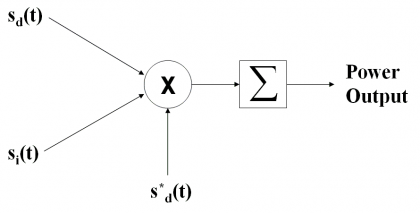
The Spectral Separation Coefficients, or SSCs for short, are a very powerful figure to indicate and measure the degree of interference that a signal suffers due to other signals sharing the band. This degradation is evaluated in terms of reduction of the Signal to Noise plus Interference Ratio (SNIR) of the desired signal, measured at the output of a receiver’s correlator that uses an ideal matched filter to receive the navigation signals as described by [J.-L. Issler et al., 2003][1], [J.W. Betz, 2001][2] and [A.R. Pratt and J.I.R. Owen, 2003][3]. Indeed, the methodology to compute the SSCs relies on the idea of measuring the power of the desired signal and its reduction due to all the interfering signals, at the correlator’s output. This can graphically be shown in the following scheme
where [math]\displaystyle{ s_d\left(t\right) }[/math] refers to the desired signal, [math]\displaystyle{ s_i\left(t\right) }[/math] to the interfering signal and [math]\displaystyle{ s_d^*\left(t\right) }[/math] is the matched spreading waveform of the desired signal. Moreover, the sum module represents the integration and dump function. This is the general model that we can find in the literature [J.J. Spilker, 1997][4]. It is also important to note that this model implies that the receiver does not make use of any cancellation technique.
Another interesting interpretation of the SSC is to see it as the mean power of the crosscorrelation function between the desired and the interfering signal [J.-L. Issler et al., 2003] [1]. For this reason, also expressions for the crosscorrelation function in the frequency and time domain are derived in the next lines.
As shown in [A.R. Pratt and J.I.R. Owen, 2003][3], the SSC provides a measure of the noise power output by a receiver when certain signals are incident at its input. As one can imagine, the better the isolation of a signal with the rest of signals in the band, the lower will be the equivalent noise caused by them, resulting thus the concept of cross power spectral density here of special interest.
If we take a closer look at Figure 1, it is possible to see that the power spectrum at the output of the correlator of a filter [math]\displaystyle{ H\left(\omega\right) }[/math] matched to the desired signal – being thus [math]\displaystyle{ H\left(\omega\right) }[/math] equal to the conjugate of the desired signal spectrum [math]\displaystyle{ S_d^*\left(\omega\right) }[/math] – can be expressed as follows:
where Pi refers to the power level of the interfering signal and [math]\displaystyle{ P_d }[/math] that of the desired signal. Moreover, in a general case a protection filter can also be included in the expression as shown in [A.R. Pratt and J.I.R. Owen, 2003] [3]. It is also important to see that the spectral definition above encompasses both the spreading codes as well as the spreading waveform of the desired and interfering signals, being thus valid for the most general case.
The power spectral density can thus be expressed as follows:
what can be further simplified yielding:
if we assume that the interfering signal and the desired signal are uncorrelated, averaging thus the cross-spectrum term to zero. This can be achieved either by means of the signal structure or the code structure being thus this assumption also true even if we work with signals of the same family, as long as all the codes are ideally orthogonal. As we can imagine, this is a very strong assumption since especially for the case of intra-system interference of signals with short codes this approximation could lead to wrong results.
Moreover, it is important to note that the functions [math]\displaystyle{ G_i\left(\omega\right) }[/math] and [math]\displaystyle{ G_d\left(\omega\right) }[/math] are both normalized Power Spectral Densities. Thus, the total power at the output of the correlator will be the integral of the output spectrum, expressed as follows:
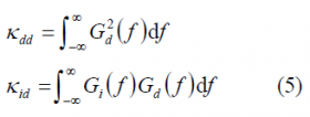
where we can recognize the spectral separation coefficient [math]\displaystyle{ k_{dd} }[/math]of the desired signal with itself and between the desired signal and the interfering signal [math]\displaystyle{ k_{id} }[/math]. These are defined as:
where the receiver and transmitter are assumed to have infinite bandwidth. If this is not the case, either the integration limits require adjustment or corrections to the SSCs must be made to include the effects of the finite bandwidths of receiver and transmitter.
We can obtain the same expressions reasoning in a different way. If we assume that the undesired signal is stochastic and Gaussian with a normalized power spectral density [math]\displaystyle{ G_i\left(f\right) }[/math] and that the desired signal can also be characterized adequately as an independent stochastic process with normalized [math]\displaystyle{ G_d\left(f\right) }[/math], then the multiplier output will be Gaussian and it is shown to be the convolution of both power spectral densities, according to:
such that after the Integrate and Dump (I&D) operator we will have:
where [math]\displaystyle{ H_{ID}\left(f\right)=sinc\left(\pi f T_I\right) }[/math] being [math]\displaystyle{ T_I }[/math] the coherent integration time.
According to this, if the interference is Additive White Gaussian Noise (AWGN) then the I&D output will be [math]\displaystyle{ N_0 \left | T_IH_{ID}\left(f\right) \right \vert ^2 }[/math] and thus the correlation sum variance will adopt the value [math]\displaystyle{ N_0T_I }[/math]. On the other hand, for the interesting case of non-white interference the output is shown to be:
For the case that the multiplier output Power Spectral Density is sufficiently flat across the I&D filter, that is for very long pseudorandom noise codes, the computation of the spectral separation is shown to approximate to the following expression:
where [math]\displaystyle{ \otimes }[/math] represents the convolution operator. Moreover, if we include the effect of the filtering at the receiver, the simplified SSC will adopt the following form:
where
- [math]\displaystyle{ G_i\left(f\right) }[/math] stands for the normalized power spectral density of the aggregate interference,
- [math]\displaystyle{ G_d\left(f\right) }[/math] is the normalized power spectral density of the desired signal, and
- [math]\displaystyle{ H_{RX}\left(f\right) }[/math] is the receiver transfer function
This equation is not applicable when the desired signal and aggregate interference are line-like. The inner product is not generally applicable when desired signals and interference have line-like spectra. Therefore, for each particular problem we have to see if the multiplier output PSD is smooth enough to justify the approximation above.
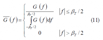
Furthermore, if we normalize the power spectral densities of the desired and interfering signals as defined in (11) (see Autocorrelation & Power Spectral Density)
the SSC adopts the following form for the case of an infinite integration time, as a function of Doppler:
Where [math]\displaystyle{ \delta f }[/math] indicates the Doppler difference at receiver level between the desired signal and the interfering signal. In addition, if an ideal filter of amplitude 1 is considered, we can express (12) also as follows:
Once we have derived a general expression for the Spectral Separation Coefficient and found useful approximations. As we have seen in (4), there is a fundamental element of the SSC that is defined as:
This expression is of great interest since it will help us in finding the main interactions between the interfering spectrum and the desired signal spectrum by simply observing its behaviour in the frequency domain. Moreover, if we expand (14) expressing the power spectral density of each of the signals in terms of their autocorrelation, we see that:
and therefore
which is shown [A.R. Pratt and J.I.R. Owen, 2003][3] to reduce to the simplified form:
In other words, the autocorrelation function of the cross power is the convolution of the interfering and desired signals. In addition, applying the Weiner-Kinchine spectrum theorem as shown in [A.R. Pratt and J.I.R. Owen, 2003][3], yields:
Using this expression, we can calculate the cross SSC, namely [math]\displaystyle{ k_{id} }[/math], in the same manner:
References
- ^ a b [J.-L. Issler et al., 2003] J.-L. Issler, L. Ries, L. Lestarquit, O. Nouvel, Q. Jeandel, Spectral measurements of GNSS Satellite Signals: Need for wide transmitted bands, Proceedings of the International Technical Meeting of the Satellite Division of the Institute of Navigation, ION-GNSS 2003, September 2003, Portland, Oregon, USA, 2003.
- ^ [J.W. Betz, 2001] J. W. Betz, Effect of Partial-Band Interference on Receiver Estimation of C/N0: Theory, Proceedings of the National Technical Meeting of the Institute of Navigation ION-NTM 2001, pp. 16-27, 22-24 January. 2001, Long Beach, California, USA.
- ^ a b c d e [A.R. Pratt and J.I.R. Owen, 2003] Anthony R. Pratt & John I.R. Owen, BOC Modulations Waveform, Proceedings of the International Technical Meeting of the Institute of Navigation, ION-GNSS 2003, 9-12 September 2003, Portland, Oregon, USA.
- ^ [J.J. Spilker, 1997] J.J. Spilker, Fundamentals of Signal Tracking Theory in Global Positioning System: Theory and Applications Volume I, Progress in Astronautics and Aeronautics Volume 164, AIAA, pp. 245-328.
Credits
The information presented in this NAVIPEDIA’s article is an extract of the PhD work performed by Dr. Jose Ángel Ávila Rodríguez in the FAF University of Munich as part of his Doctoral Thesis “On Generalized Signal Waveforms for Satellite Navigation” presented in June 2008, Munich (Germany)


