If you wish to contribute or participate in the discussions about articles you are invited to contact the Editor
Power Spectral Density of the AltBOC Modulation: Difference between revisions
Carlos.Lopez (talk | contribs) No edit summary |
Carlos.Lopez (talk | contribs) No edit summary |
||
| Line 322: | Line 322: | ||
==References== | ==References== | ||
<references/> | <references/> | ||
== Credits == | |||
The information presented in this NAVIPEDIA’s article is an extract of the PhD work performed by Dr. Jose Ángel Ávila Rodríguez in the FAF University of Munich as part of his Doctoral Thesis “On Generalized Signal Waveforms for Satellite Navigation” presented in June 2008, Munich (Germany) | |||
[[Category:Fundamentals]] | [[Category:Fundamentals]] | ||
[[Category:GNSS Signals]] | [[Category:GNSS Signals]] | ||
Latest revision as of 09:16, 25 November 2011
| Fundamentals | |
|---|---|
| Title | Power Spectral Density of the AltBOC Modulation |
| Author(s) | J.A Ávila Rodríguez, University FAF Munich, Germany. |
| Level | Advanced |
| Year of Publication | 2011 |
In the next lines the power spectral density of the AltBOC modulation will be derived. We will analyze the most general expressions that apply when data and pilot are considered, using thus four different codes. First, the expressions with no constant envelope are obtained and then the modified constant envelope version is studied and compared with that derived in [E. Rebeyrol et al., 2005][1]
It is assumed that the AltBOC signal is stationary in wide sense and that the PRN codes are ideal. A slight modification of the codes is necessary to consider that the sub-carrier is included in the chip waveform when the ratio [math]\displaystyle{ \Phi=2f_s/f_c }[/math] (see Binary Offset Carrier (BOC)). Since Galileo will be transmitting AltBOC(15,10) in E5 and thus the ratio [math]\displaystyle{ \Phi }[/math] is odd, we will pay special attention to this particular case deriving the expressions of AltBOC for both the even and odd cases.
The AltBOC modulation can be defined as follows [E. Rebeyrol et al., 2005][1]:
where [math]\displaystyle{ C_L^D }[/math] is the lower data code, [math]\displaystyle{ C_L^P }[/math] is the lower pilot code, [math]\displaystyle{ C_U^D }[/math] the upper data code and [math]\displaystyle{ C_U^P }[/math] the upper pilot code. [math]\displaystyle{ S_{AltBOC}\left(t\right) }[/math] can also be expressed as follows:
where
and
Using now the expressions above, the autocorrelation of AltBOC yields:
If we assume now again that the crosscorrelation between the different codes is equal to zero and that the complex crosscorrelations cancel each other out, the power spectral density of the AltBOC modulation is then shown to be:
where [math]\displaystyle{ A\left(f\right) }[/math] and [math]\displaystyle{ B\left(f\right) }[/math] are the Fourier Transforms of [math]\displaystyle{ sign[cos\left(2\pi f_st\right)] }[/math] and [math]\displaystyle{ sign[sin\left(2\pi f_st\right)] within a chip of length \lt math\gt T_c }[/math]. This means in other words that [math]\displaystyle{ G_A\left(f\right) }[/math] and [math]\displaystyle{ G_B\left(f\right) }[/math] are the power spectral densities of the cosine-phased and sine-phased BOC modulations that we have derived in Appendixes B and C. As we know, the expression of [math]\displaystyle{ G_A\left(f\right) }[/math] and [math]\displaystyle{ G_B\left(f\right) }[/math] depends on whether the ratio [math]\displaystyle{ \Phi }[/math] is even or odd and thus to have the general expression of the AltBOC signal we also have to distinguish between these two cases.
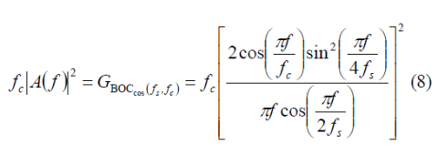
The normalized power spectral density of the cosine-phased BOC modulation for the ratio [math]\displaystyle{ \Phi }[/math] even is:
and for [math]\displaystyle{ \Phi }[/math] odd
The normalized power spectral density of the sine-phased BOC modulation for [math]\displaystyle{ \Phi }[/math] even is:
and for [math]\displaystyle{ \Phi }[/math] odd
Using these results, the normalized power spectral density of the AltBOC modulation is then shown to adopt the following expression for [math]\displaystyle{ \Phi }[/math] even:
which can be further simplified as follows:
which coincides perfectly with the expression derived in [E. Rebeyrol et al., 2005][1]. If we do the same now for the odd case, we obtain the following expression:
or equivalently,
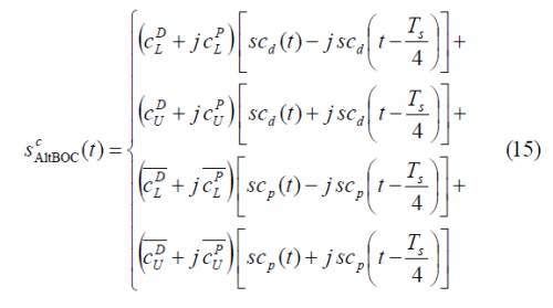
Once we have derived the general AltBOC expressions for the case of non-constant envelope, we concentrate now on the modified AltBOC modulation with constant envelope. In order to distinguish it from the general form, we will write the superindex c for constant envelope. The modified AltBOC signal waveform with constant envelope can be expressed as follows:
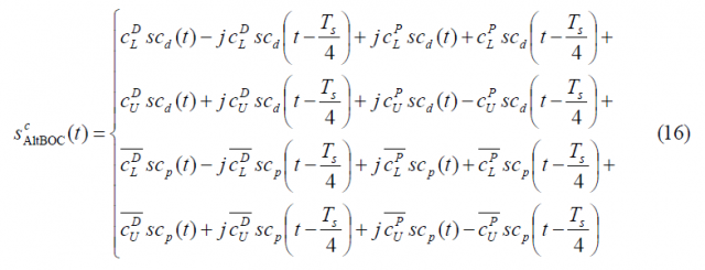
where the superindex indicates constant envelope. Furthermore, [math]\displaystyle{ T_s }[/math] is the in inverse of the sub-carrier frequency. According to this expression, [math]\displaystyle{ s_{AltBOC}\left(t\right) }[/math] can be further expanded as
where
and the data and pilot sub-carriers can be expressed as:
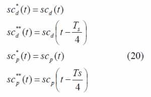
To facilitate now the analyses in the next lines let us rename the following signals in line with the approach followed in [E. Rebeyrol et al., 2005][1]. Thus:
If we calculate now the autocorrelation function of [math]\displaystyle{ \mathfrak{R}_{AltBOC}^c\left(\tau\right) }[/math], we can clearly recognize that most of the terms cancel out since we have assumed that the codes are ideally orthogonal with each other. Additionally, the cross-correlation between the data and pilot sub-carriers, namely [math]\displaystyle{ sc_d }[/math] and [math]\displaystyle{ sc_p }[/math], will also be zero. In addition, the cross-correlations of each data and pilot sub-carrier correlates to zero with a delayed version of themselves by [math]\displaystyle{ T_s/4 }[/math] (and actually also with [math]\displaystyle{ 3T_s/4 }[/math]). As a result, [math]\displaystyle{ \mathfrak{R}_{AltBOC}^c\left(\tau\right) }[/math] will simplify as follows:
Since all the codes are of the same length and they do ideally correlate as expected from ideal random codes, the power spectral density of the modified constant envelope AltBOC modulation can be expressed as shown next:
or also
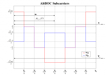
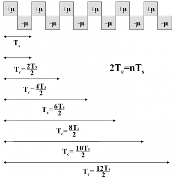
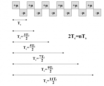
where [math]\displaystyle{ SC_d^*\left(f\right) }[/math], [math]\displaystyle{ SC_d^{**}\left(f\right) }[/math], [math]\displaystyle{ SC_p^*\left(f\right) }[/math] and [math]\displaystyle{ SC_p^{**}\left(f\right) }[/math]are the Fourier Transforms of [math]\displaystyle{ SC_d^* }[/math],[math]\displaystyle{ SC_d^{**} }[/math],[math]\displaystyle{ SC_p^* }[/math] and [math]\displaystyle{ SC_p^{**} }[/math] respectively and consequently [math]\displaystyle{ G_d^*\left(f\right) }[/math],[math]\displaystyle{ G_d^{**}\left(f\right) }[/math],[math]\displaystyle{ G_p^*\left(f\right) }[/math] and [math]\displaystyle{ G_p^{**}\left(f\right) }[/math] are the respective power spectral densities. We recall that the subindexes d and p indicate whether we refer to the data or pilot carrier and the super-index whether we work with the prompt or the delayed version. To make progress in our derivations it is necessary to calculate first the Fourier Transforms of the data and pilot sub-carriers. Let us begin now with the calculation of the Fourier Transform of [math]\displaystyle{ SC_d^* }[/math] over [math]\displaystyle{ [0,T_c] }[/math]. To facilitate the understanding, we show again the shape of the AltBOC sub-carriers in the next figures:
We can define now the prompt data sub-carrier piecewise as follows:
where
It is important to remember that depending on whether the number of times that m fits in n (see previous Figure) is even or odd we will have the even version of the constant envelope AltBOC modulation or the odd version. Indeed, we can employ here again the figure [math]\displaystyle{ \Phi=2f_s/f_c }[/math] to make this distinction, where [math]\displaystyle{ \Phi }[/math] can be seen as the number of half periods within a chip.
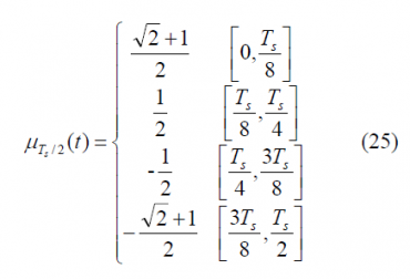
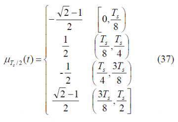
To obtain the Fourier Transform of the prompt data sub-carrier, we derive first the Fourier Transform of the auxiliary signal [math]\displaystyle{ \mu_{T_s/2} }[/math]. This is shown to be:
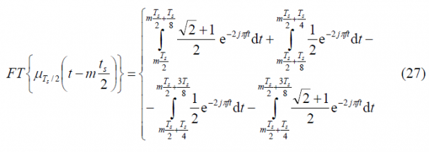
which can be expanded as follows:
Fortunately this complex expression can be further simplified and adopts the following form:
As a result, the Fourier Transform of the prompt data sub-carrier can be expressed in terms of the equation above as:
As we can immediately recognize, the sum term will be different depending on whether [math]\displaystyle{ \Phi }[/math] is even or odd. In order to have first the most general expression of the constant envelope AltBOC modulation we will not develop this expression any further until all the terms contributing to the computation of AltBOC are obtained.
Summarizing, the power spectral density of the prompt data sub-carrier can be expressed for the general case as follows:
If we repeat now for the delayed data sub-carrier [math]\displaystyle{ SC_d^{**}\left(t\right) }[/math] we have then:
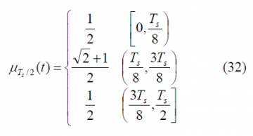
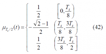
where in this case the [math]\displaystyle{ \mu_{T_s/2} }[/math] function is defined as follows:
so that,
and therefore
As we can see, the sum term of the expression above is similar to that of the prompt data sub-carrier adopting the power spectral density of the delayed data sub-carrier the following form in the general case:
We repeat now for the prompt pilot sub-carrier [math]\displaystyle{ SC_p^*\left(t\right) }[/math] in a similar way:
with
According to this, the Fourier Transform can be obtained from:
yielding thus:
As we can recognize, the sum term is fortunately again the same and thus the power spectral density will be:
Finally, we calculate the Fourier Transform of the delayed pilot sub-carrier. This can be defined as follows:
with
being its Fourier Transform defined as follows:
such that:
Once again, the sum term is the same as that of the previous derivations and we can easily express the power spectral density for the general case as:
Once we have obtained the individual elements that form the constant envelope AltBOC modulation, we can express the power spectral density for the general case as follows:
or equivalently,
what can be further simplified to:
Until now, all the derived expressions are valid for both the even and odd case. However, as we can immediately recognize from the expression derived above, the common sum term will be different depending on whether [math]\displaystyle{ \Phi }[/math] is even or odd. In order to have a clearer view of the two cases to analyze, we present in the next figures how one could integrate the sub-carrier in the chip waveform for the two cases of [math]\displaystyle{ \Phi }[/math].
As we can see, for both cases the following relationship remains true:
If we solve the sum term first for [math]\displaystyle{ \Phi }[/math] even we have:
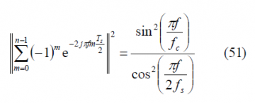
since [math]\displaystyle{ \left(-1\right)^n }[/math] for n even is always 1. We can further simplify the expression above if we recall the relationship between the sub-carrier and the code frequency. In fact, the square of the absolute value adopts the following form if [math]\displaystyle{ \Phi }[/math] is even:
Equally, for the case of [math]\displaystyle{ \Phi }[/math] odd we have:
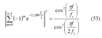
since [math]\displaystyle{ \left(-1\right)^n }[/math] for n odd is always -1. Moreover, since the relationship [math]\displaystyle{ n=2f_s/f_c }[/math] is also valid when [math]\displaystyle{ \Phi }[/math] is odd, we can further simplify the previous expression as shown next:
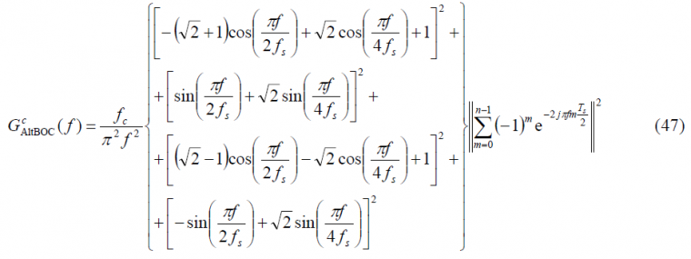
If we now put all the partial results of the lines above together, we can express the power spectral density of the modified even constant envelope AltBOC modulation as follows:
while for the odd case we will have:
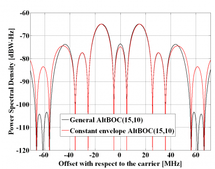
which is the well-known expression of the normalized power spectral density of the constant envelope AltBOC modulation when [math]\displaystyle{ \Phi }[/math] is odd. In the next figure we show the two analyzed versions of the AltBOC modulation, namely the general expression and the constant envelope modified version with a sub-carrier frequency of 15.345 MHz and a code frequency of 10.23 MHz.
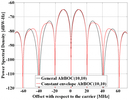
Equally, for an AltBOC(10,10) – thus with [math]\displaystyle{ \Phi }[/math] even – the difference between the general AltBOC and the constant envelope solution is shown to be minimum:
It is interesting to note that the power spectral densities of the general AltBOC modulation and the modified constant envelope AltBOC have similar shapes and only minor differences can be observed in the high order lobes. Indeed, the main and first side lobes are nearly identical being the differences lower than 1 dB. The only differences can be observed in the high frequency components and come from the extra terms that are needed to achieve constant envelope. Nonetheless in real implementations these would be filtered after amplification and thus for most of the bandwidths of interest we can state that there is no qualitative difference between both solutions regarding the spectrum. In terms of implementation, however, it is clear that the constant envelope solution is superior.
References
- ^ a b c d [E. Rebeyrol et al., 2005] E. Rebeyrol, C. Macabiau, L. Lestarquit, L. Ries, J-L. Issler, M.L. Boucheret, M. Bousquet , BOC Power Spectrum Densities, Proceedings of the National Technical Meeting of the Institute of Navigation, ION-NTM 2005, 24-26 January 2005, Long Beach, California, USA.
Credits
The information presented in this NAVIPEDIA’s article is an extract of the PhD work performed by Dr. Jose Ángel Ávila Rodríguez in the FAF University of Munich as part of his Doctoral Thesis “On Generalized Signal Waveforms for Satellite Navigation” presented in June 2008, Munich (Germany)


