If you wish to contribute or participate in the discussions about articles you are invited to contact the Editor
Time-Multiplexed BOC (TMBOC)
| Fundamentals | |
|---|---|
| Title | Time-Multiplexed BOC (TMBOC) |
| Author(s) | J.A Ávila Rodríguez, University FAF Munich, Germany. |
| Level | Advanced |
| Year of Publication | 2011 |
TMBOC Implementation
In a TMBOC spreading time series [G.W. Hein et al., 2006][1], different BOC spreading symbols are used for different chip values, in either a deterministic or periodic pattern. To produce an MBOC(6,1,1/11) spectrum, the used spreading symbols are BOC(1,1) chips, denoted as [math]\displaystyle{ g_{BOC\left(1,1\right)}\left(t\right) }[/math], and BOC(6,1) chips, denoted as [math]\displaystyle{ g_{BOC\left(6,1\right)}\left(t\right) }[/math], where
and
Since the pilot and data components of a signal can be formed using different spreading time series, and the total signal power can be divided differently between the pilot and data components, many different TMBOC-based implementations are possible.
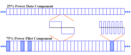
The selected TMBOC implementation is a signal with 75 % power on the pilot component and 25 % power on the data component, such that all the BOC(1,1) spreading symbols are used for the data, since data demodulation does not benefit from the higher frequency contributions of BOC(6,1). On the other hand, the pilot component time series comprises 29/33 BOC(1,1) spreading symbols and 4/33 BOC(6,1) spreading symbols. This design places all of the higher frequency contributions in the pilot component, providing the greatest possible benefit to signal tracking when only the pilot channel is used to this purpose.
Figure 1 next shows the BOC(6,1) spreading symbols in locations 1, 5, 7, and 30 of each 33 spreading symbol locations. This pattern will be repeated 310 times since the spreading code is 10230 chips long.
Several considerations affect the choice of the specific locations of the BOC(6,1) spreading symbols. For example, if the BOC(6,1) chips were placed in both the pilot and data components, the receiver implementation would be more simple than if these symbols were placed in the same locations in both. In addition, the proper placement of the BOC(6,1) symbols leads to an improvement of the spreading codes’ autocorrelation and crosscorrelation properties of approximately 1 dB, compared to those that can be observed when only BOC(1,1) spreading symbols are used. The good results obtained for L1C using the BOC(6,1) locations and the performance of the spreading codes for L1C [G.W. Hein et al., 2006] [1] confirm the optimality of the described positions of BOC(6,1).
Finally, we show in the next table the correlation losses that result from correlating a BOC(1,1) replica with different implementations of MBOC, included the finally selected for GPS.
Analysing the two possible implementations of MBOC, namely CBOC and TMBOC, it can be concluded that there are no significant differences of performance between both as this depends actually on the final user configuration. Indeed, how good or bad placing all the high frequency BOC(6,1) component on both data and pilot or only on the pilot channel is depends on the particular application. In addition, from the point of view of the correlation characteristics, the TMBOC provides an additional improvement of 1 dB in terms of reduced correlation if the BOC(6,1) component is placed at proper locations, what further improves the noise input.
References
- ^ a b [G.W. Hein et al., 2006] G. W. Hein, J.-A. Avila-Rodriguez, S. Wallner, A.R. Pratt, J.I.R. Owen, J.-L Issler, J.W. Betz, C.J. Hegarty, S. Lenahan, J.J. Rushanan, A.L. Kraay, T.A. Stansell, MBOC: The New Optimized Spreading Modulation Recommended for Galileo L1 OS and GPS L1C, Proceedings of the International Technical Meeting of the Institute of Navigation, IEEE/ION PLANS 2006, 24-27 April, 2006, Loews Coronado Bay Resort, San Diego, California, USA.
Credits
The information presented in this NAVIPEDIA’s article is an extract of the PhD work performed by Dr. Jose Ángel Ávila Rodríguez in the FAF University of Munich as part of his Doctoral Thesis “On Generalized Signal Waveforms for Satellite Navigation” presented in June 2008, Munich (Germany)


