If you wish to contribute or participate in the discussions about articles you are invited to contact the Editor
SBAS Fundamentals: Difference between revisions
Carlos.Lopez (talk | contribs) No edit summary |
mNo edit summary |
||
| (3 intermediate revisions by 3 users not shown) | |||
| Line 1: | Line 1: | ||
{{Article Infobox2 | {{Article Infobox2 | ||
|Category=Fundamentals | |Category=Fundamentals | ||
|Editors=GMV | |Editors=GMV | ||
|Level=Basic | |Level=Basic | ||
|YearOfPublication=2011 | |YearOfPublication=2011 | ||
|Logo=GMV | |||
|Title={{PAGENAME}} | |Title={{PAGENAME}} | ||
}} | }} | ||
| Line 209: | Line 210: | ||
* Compatibility to other avionics equipment, in particular Flight Management Systems (FMS). | * Compatibility to other avionics equipment, in particular Flight Management Systems (FMS). | ||
The SoL civil aviation certified equipment is in the highest rank with respect its cost. There exist a large number of certified receivers manufacturers worldwide both in the US (GARMIN, Honeywell, Rockwell Collins, General Avionics, etc) and in Europe (see complete list in EASA homepage<ref>[ | The SoL civil aviation certified equipment is in the highest rank with respect its cost. There exist a large number of certified receivers manufacturers worldwide both in the US (GARMIN, Honeywell, Rockwell Collins, General Avionics, etc) and in Europe (see complete list in EASA homepage<ref>[https://www.easa.europa.eu/ List of ETSO Authorisations (European Aviation Safety Agency)]</ref>). | ||
The Open Service (OS) targets low cost, general purpose GNSS equipment that uses the SBAS SIS to provide the user with an enhanced accuracy performance in comparison with the one provided by a standalone GPS device. In comparison with the certification requirements of the user equipment above, user equipment is not necessarily compliant with the RTCA MOPS DO 229 processing rules, but might only make use of the processing algorithms that render the accuracy corrections provided by the SBAS SIS. | The Open Service (OS) targets low cost, general purpose GNSS equipment that uses the SBAS SIS to provide the user with an enhanced accuracy performance in comparison with the one provided by a standalone GPS device. In comparison with the certification requirements of the user equipment above, user equipment is not necessarily compliant with the RTCA MOPS DO 229 processing rules, but might only make use of the processing algorithms that render the accuracy corrections provided by the SBAS SIS. | ||
| Line 222: | Line 223: | ||
[[Category:Fundamentals]] | [[Category:Fundamentals]] | ||
[[Category:Other SBAS]] | [[Category:Other SBAS|!]] | ||
Latest revision as of 08:34, 27 July 2018
| Fundamentals | |
|---|---|
| Title | SBAS Fundamentals |
| Edited by | GMV |
| Level | Basic |
| Year of Publication | 2011 |
A Satellite-based Augmentation System (SBAS) is a civil aviation safety-critical system that supports wide-area or regional augmentation – even continental scale - through the use of geostationary (GEO) satellites which broadcast the augmentation information.[1][2] A SBAS augments primary GNSS constellation(s) by providing GEO ranging, integrity and correction information. While the main goal of SBAS is to provide integrity assurance, it also increases the accuracy with position errors below 1 meter (1 sigma).
The ground infrastructure includes the accurately-surveyed sensor stations which receive the data from the primary GNSS satellites and a Processing Facility Center which computes integrity, corrections and GEO ranging data forming the SBAS signal-in-space (SIS). The SBAS GEO satellites relay the SIS to the SBAS users which determine their position and time information. For this, they use measurements and satellite positions both from the primary GNSS constellation(s) and the SBAS GEO satellites and apply the SBAS correction data and its integrity.
The augmentation information provided by SBAS covers corrections and integrity for satellite position errors, satellite clock/time errors and errors induced by the estimation of the delay of the signal while crossing the ionosphere. For the errors induced by the estimation of the delay caused by the troposphere and its integrity, the user applies a tropospheric delay model.
SBAS Signal
Every SBAS provides ranging signals transmitted by GEO satellites, differential corrections on the wide area and additional parameters aimed to guarantee the integrity of the GNSS user:
- GEO Ranging: transmission of GPS-like L1 signals from GEO satellites to augment the number of navigation satellites available to the users.
- Wide Area Differential (WAD): differential corrections to the existing GPS/GLONASS/GEO navigation services computed in a wide area to improve navigation services performance. This includes corrections to the satellite orbits and clocks, as well as information to estimate the delay suffered from the signal when it passes through the ionosphere.
- GNSS/Ground Integrity Channel (GIC): integrity information to inform about the availability of GPS/GLONASS/GEO safe navigation service.
The SBAS delivers to the user the corrections and integrity data as well as some ancillary information (timing, degradation parameters, etc.) through messages encoded in the signal. The specification of the SBAS message data format is contained in the ICAO SARPS Appendix B for the aspects related with the signal in space, as well as in the RTCA MOPS DO-229D for the minimum performance requirements applicable to the airborne SBAS receiver equipment. The format of the messages is thoroughly explained in the article The EGNOS SBAS Message Format Explained.
The SBAS satellite shall transmit a GPS-like L1 (1574.42 MHz) signal, modulated with a Coarse/Acquisition Pseudo-Random Noise (PRN) code. The SBAS L1 radiofrequency characteristics are:[3]
| Parameter | Description |
|---|---|
| Modulation | Bi-phase shift key (BPSK) modulated by a bit train comprising the PRN code and the SBAS data (modulo-2 sum). |
| Bandwidth | L1 ±30.69 MHz. At least 95% of the broadcast power will be contained within the L1 ±12 MHz band. |
| Ranging Codes | A PRN Code (Gold code) of 1 millisecond in length at a chipping rate of 1023 Kbps. |
| SBAS Data | 500 symbols per second, module-2 modulated (250 effective bits per second) |
| Power | Minimum power –131 dBm at 5 degrees elevation Maximum power –119,5 dBm |
A convolutional encoding of the bits is performed with the following parameters:
| Code Parameter | Value |
|---|---|
| Coding Rate | 1/2 |
| Coding Scheme | Convolutional |
| Constraint Length | 7 |
| Generator Polynomials | G1 = 171(oct); G2 = 133(oct) |
| Encoding Sequence | G1 then G2 |
| Flush | No |
SBAS Performances
The SBAS performances are defined with respect to the level of service that the system is designed to provide. The main source for SBAS performances comes from civil aviation navigation safety requirements and they are different for each civil aviation operation.[3]
| Typical Operation | Horizontal Accuracy (95%) | Vertical Accuracy (95%) | Integrity | Time-To-Alert (TTA) | Continuity | Availability |
|---|---|---|---|---|---|---|
| En-route | 3.7 km (2.0 NM) | N/A | 1 – 1 × 10⁻⁷/h | 5 min | 1 – 1 × 10⁻⁴/h to 1 – 1 × 10⁻⁸/h | 0.99 to 0.99999 |
| En-route Terminal | 0.74 km (0.4 NM) | N/A | 1 – 1 × 10⁻⁷/h | 15 s | 1 – 1 × 10⁻⁴/h to 1 – 1 × 10⁻⁸/h | 0.99 to 0.99999 |
| Initial approach, Intermediate approach, Non-precision approach (NPA), Departure | 220 m (720 ft) | N/A | 1 –1x10⁻⁷/h | 10 s | 1 – 1x10⁻⁴/h to 1 – 1x10⁻⁸/h | 0.99 to 0.99999 |
| Approach operations with vertical guidance (APV-I) | 16 m (52 ft) | 20 m (66 ft) | 1 – 2 × 10⁻⁷ per approach | 10 s | 1 – 8 × 10⁻⁶ in any 15 s | 0.99 to 0.99999 |
| Approach operations with vertical guidance (APV-II) | 16 m (52 ft) | 8 m (26 ft) | 1 – 2 × 10⁻⁷ per approach | 6 s | 1 – 8 × 10⁻⁶ in any 15 s | 0.99 to 0.99999 |
| Category I precision Approach | 16 m (52 ft) | 6.0 m to 4.0 m (20 ft to 13 ft) | 1 – 2 × 10⁻⁷ per approach | 6 s | 1 – 8 × 10⁻⁶ in any 15 s | 0.99 to 0.99999 |
As indicated in the table above, the performance requirements are expressed in terms of four quantitative concepts, many of them to be interpreted as probabilistic figures:
- Accuracy: is expressed in terms of Navigation System Error (NSE) as the difference between the real position of the aircraft and the position provided by the airborne equipment. A SBAS assures the compliance with respect the accuracy requirements by providing to the user corrections to the satellite orbit and clock errors as well as to the ionospheric residual propagation error. For LPV200 operations, new requirements have been proposed distinguishing the fault-free and the system failure conditions.[4]
- Integrity: is defined by ICAO as a measure of the trust that can be placed in the correctness of the information supplied by the system.[3] This general statement is expressed at the SBAS system level as the maximum allowable probability that the navigation position error exceeds alarm limit and the navigation system does not alert the pilot in a time less than the time to alert. The SBAS assures the integrity requirements by:
- Providing to the user satellite and/or ionospheric alarms in order to inform the user to reject the corresponding satellite/ionospheric corrections in its positioning computation.
- Providing to the user Horizontal and Vertical Protection Level information (HPL, VPL) in order to assess the availability of the system, by comparing these PLs with the corresponding Alarm Limits (AL) for a given phase of flight (see next table). The SBAS computes and broadcasts integrity bounds to the satellite orbit and clock (UDRE) corrections as well as to the ionospheric corrections errors (GIVE) so that the user is able to compute a PL that over bounds the navigation system error experienced by the user with the integrity risk requirement.
| Operation | Horizontal AL | Vertical AL |
|---|---|---|
| En-route (oceanic/continental) | 7.4 Km (4 NM) | N/A |
| En-route (continental) | 3.7 Km (2 NM) | N/A |
| En-route, Terminal | 1.85 Km (1 NM) | N/A |
| NPA | 556 m (0.3 NM) | N/A |
| APV-I | 40 m (130 ft) | 50 m (164 ft) |
| LPV200 | 40 m (130 ft) | 35 m (200 ft) |
| APV-II | 40 m (130 ft) | 20 m (66 ft) |
| Category I | 40 m (130 ft) | 15 to 10 m (50 ft to 33 ft) |
- Continuity: is the probability that the specified system performance will be maintained for the duration of a phase of operation, presuming that the system was available at the beginning of that phase of operation and was predicted to operate throughout the operation.[3] Lack of continuity means that the operation must be aborted (with the associated risk).
- Availability: is the probability that the navigation service is available at the beginning of the planned operation. A SBAS is considered available when the accuracy, integrity and continuity requirements are met and it is measured in terms of probability of the system being available for any given user at any given time. In practice, the availability is computed by measuring the probability of a protection level being below its corresponding alarm limit. It should be noted that a lack of availability is not a safety concern but prevents the nominal operation of the system, and implies an associated impact on the service operation status.
SBAS Architecture
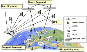
A SBAS is a safety critical system designed to augment one or several satellite navigation systems. In this sense, it is not a standalone system. The main layers of a general SBAS architecture are:
- Space segment comprising the geostationary satellites (GEO) with navigation payloads in charge of transmitting a GPS-like carrier signal with the SBAS information.
- Ground segment comprising all the ground elements in charge of the provision of the SBAS navigation message. The main elements are:
- Monitoring Station Network.
- Processing Facility Center.
- GEO Satellite Control Center.
- Communication Layer.
- Support segment comprising all the elements need to support the correct operation and maintenance of the SBAS: configuration control, performance evaluation, maintenance and development, help desk, etc.
- User segment comprising all the user equipment needed to receive and use the SBAS information.
Space segment
The SBAS space segment is composed by several geostationary satellites in charge of broadcasting, over the service area, the SBAS navigation message. Typically, the SBAS satellites are multi-purpose (commercial communication) satellites that carry out an additional navigation payload capable to generate a GPS-like signal that retransmits to the users the navigation message generated on-ground.
The SBAS GEO navigation payload is a transponder that relays the on-ground generated signal (upload to the GEO in the C-band frequency) to a transmitted signal in the L-band frequency band. For most of the navigation payloads, a second C-band downlink channel is available in order to improve the adjustment of the signal delay due to atmospheric propagation. However, first generation of navigation payloads only included a single-channel frequency translating repeater.
The new generation of SBAS navigation payload includes more advanced functionalities. Among them, it is worth noting:
- Increase of the emission bandwidth and broadcast power.
- Evolution to dual-frequency L1/L5 transponders.
- Evolution of payload from signal transponders to regenerative payloads in which the signal is entirely build up onboard (the GEO only receives from ground segment the navigation message to be modulated in the GEO signal).
Ground Mission Segment
The main purpose of the Ground Mission Segment is to generate and uplink the augmentation signal that will be broadcast by the GEO satellite.
To achieve this objective, the Ground Mission Segment is typically broken down into the following subsystems:
- Monitoring Station Network: Its purpose is to collect data from the satellites that are to be augmented. This is performed by a network of GNSS receivers.
- Processing Facility Center: It is in charge of processing the data provided by the Monitoring Station Network to generate the messages to be broadcasted to the satellites.
- GEO Satellite Control Center: It is in charge of generating the signal with the message provided by the Processing Facility Center and up-linking it to the GEO satellites.
- Communication Layer: It interconnects the different elements of the Ground Segment.
Monitoring Station Network
The Monitoring Station Network is carefully designed to monitor satellites and ionosphere with the required accuracy and availability in the SBAS service area. This usually implies a dense network of stations in the service area, with some additional stations outside. In addition, there must be redundancy to avoid single points of failure, or even different subsets of stations to feed parallel and independent processing chains.
The monitoring stations have the following characteristics:
- Dual frequency (L1/L2) receivers with geodetic quality.
- Atomic frequency standard (Caesium/Rubidium/H-Maser).
- Able to track all in view GPS and GEO satellites.
- Allocated in site conditions with good local environment condition in terms of multipath and radio frequency interference .
- Geo-referenced to WGS-84 (or ITRF) within a 1-3 cm accuracy.
- Compliant with some processing capabilities:
- 1 Hz data acquisition.
- Embedded data quality checks to remove misleading data.
- Data processing and broadcast within a few milliseconds.
- Integrated robustness against known threats (e.g. evil waveforms detection).
Processing Facility Center
The Processing Facility Center is one of the critical elements of the SBAS system as it is charge of generating the augmentation information for the user, playing a major role in the achievement of the SBAS performance requirements.
The Processing Facility Center is in charge of the following functions:
- Process all input data from the Monitoring Station Network.
- Estimate the satellite corrections, ionospheric model and error variance terms.
- Perform a dedicated integrity assessment on the information provided by the system to the users.
- Format the outputs according to the SBAS standards.
The Processing Facility Center has a very strong algorithmic load, as it has to solve the following challenges:
- Advanced models for satellite orbit determination (breaking frontiers in GEO orbit and clock determination).
- Determination of the SBAS reference time and satellite clock corrections with better than 2 ns accuracy.
- Real-time ionospheric estimation with a dense network of receivers. This estimation should be able to characterize local and rapid phenomena.
- Integrity estimation valid for wide-areas with demanding performance requirements.
GEO Satellite Control Center
GEO Satellite Control Center function is to relay the SBAS messages computed by the Processing Facility Center to the GEO satellites. Its functions include:
- Codify the GPS-like signal encoding. In particular, the preparation of the signal generation as well as the PRN encoding.
- Modulate the SBAS message information provided by the Processing Facility Center into the signal.
- Synchronize the timing of the signal to the SBAS reference time.
- Control de time synchronization between the carrier and code components of the uplink signal (core-carrier coherency).
- Close the uplink-station/GEO-satellite control loop by receiving and processing the downlink SBAS satellite signals (both in L- and C- bands).
Communication Layer
The Communication Layer ensures that all the SBAS Ground Segment elements are interconnected in real time. This connection should be performed with high performance standards in terms of reliable lines, sufficient bandwidth for a large exchange of data, and stringent redundancy and security requirements.
Support Mission Segment
The SBAS Support Segment collects all the elements need to support the development and operation of a SBAS system. These elements are not related with the provision of the SBAS service but they are needed as external support facilities. They SBAS support needs can be listed as:
- The design, development and validation phases.
- The deployment and operation.
- The certification process.
- The maintenance and troubleshooting.
- The certification of applications.
Between the different SBAS Support elements it is worth noting:
- End to End Simulators in charge of simulating data under controlled conditions (reference errors, emulated feared events) in order to simulate the real system behaviour (delays and communication problems, algorithm, broadcasting features, etc).
- Service Volume Simulators in charge of evaluating the overall SBAS performances over the service area under a set of controlled conditions.
- Performance Analysis Tools in charge of measuring all the performance concepts at:
- system level by analyzing the Signal in Space information and checking the accuracy, integrity, continuity and availability features but using concepts based in the errors available at pseudorange domain.
- user point of view level, by analyzing user data (including local conditions) and applying user-related algorithms (see SBAS standards).
- On-line monitoring tools for tracking the system behavior in real time and collecting system failure and anomalies. These elements also support the system operation by predicting the expected behavior of the system and provide warnings as system outages or degradations. They also provide warnings to external users.
- Archiving tools supporting the data archiving. The data comprises both all the internal information generated by the system as well as external data (satellite reference orbit and clock data, ionospheric information, outages, etc).
- Application test benches to support applications by generating test scenarios for their certification and performance verification. They are able to plug different application software or equipment for homologation purposes.
User Segment
The SBAS user segment comprises all the user equipment that makes use of the SBAS Signal in Space (SIS). In fact, the SBAS User segment is not under the control of the SBAS service provider as it is driven by the SBAS application market.
In general, the SBAS service operator provides different services aiming at different market sectors, namely an Open Service, a Safety of Life service (SoL) and even a Commercial Service.
For the Safety-of-Life (SoL) service, the SBAS user equipment shall be compliant (certified) against several standards. For instance, civil aviation SBAS equipment shall demonstrate (see SBAS standards):
- Full compliance to RTCA SBAS MOPS DO-229 (airborne equipment).
- Full compliance to the RTCA SBAS MOPS 228 and 301 (antenna requirements).
- Compliance to RTCA TSO (C190, C145b, C146b) for SBAS equipment.
- Compatibility to other avionics equipment, in particular Flight Management Systems (FMS).
The SoL civil aviation certified equipment is in the highest rank with respect its cost. There exist a large number of certified receivers manufacturers worldwide both in the US (GARMIN, Honeywell, Rockwell Collins, General Avionics, etc) and in Europe (see complete list in EASA homepage[5]).
The Open Service (OS) targets low cost, general purpose GNSS equipment that uses the SBAS SIS to provide the user with an enhanced accuracy performance in comparison with the one provided by a standalone GPS device. In comparison with the certification requirements of the user equipment above, user equipment is not necessarily compliant with the RTCA MOPS DO 229 processing rules, but might only make use of the processing algorithms that render the accuracy corrections provided by the SBAS SIS.
Finally, some SBAS service providers (see EGNOS) include the provision of the information computed by the SBAS ground element (input raw data, corrections, integrity information) by dissemination means different to the SBAS GEO link (generally, using terrestrial telecommunication networks). This constitutes the Commercial Service. This market sector comprises professional users (land and geodesy applications, maritime or terrestrial transport applications) that are not subject to the integrity and latency requirements needed in the SoL service.
Notes
References
- ^ Wikipedia:GNSS augmentation
- ^ E.D. Kaplan, C.J. Hegarty, Understanding GPS Principles and Applications”, 2nd Ed., Artch House, ISBN 1-58053-894-0, 2006.
- ^ a b c d ICAO Standards and Recommended Practices, Annex 10, Volume 1 Radio Navigation Aids, July 2006
- ^ NSP WGW October 2008 Report – Attachment G, Recommended changes to Annex 10, Volume 1, Section 3.7
- ^ List of ETSO Authorisations (European Aviation Safety Agency)


