If you wish to contribute or participate in the discussions about articles you are invited to contact the Editor
Electromagnetic Beam Bending: Difference between revisions
Carlos.Lopez (talk | contribs) No edit summary |
Jaume.Sanz (talk | contribs) No edit summary |
||
| Line 1: | Line 1: | ||
{{Article Infobox2 | {{Article Infobox2 | ||
|Category=Fundamentals | |Category=Fundamentals | ||
|Authors=J. Sanz Subirana, | |Authors=J. Sanz Subirana, J.M. Juan Zornoza and M. Hernández-Pajares, Technical University of Catalonia, Spain. | ||
|Level=Basic | |Level=Basic | ||
|YearOfPublication=2011 | |YearOfPublication=2011 | ||
Revision as of 11:38, 6 February 2012
| Fundamentals | |
|---|---|
| Title | Electromagnetic Beam Bending |
| Author(s) | J. Sanz Subirana, J.M. Juan Zornoza and M. Hernández-Pajares, Technical University of Catalonia, Spain. |
| Level | Basic |
| Year of Publication | 2011 |
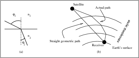
As it is known, the density of the atmospheric gas and plasma is not homogeneous. This causes spatial and temporal variations in the refraction index. Due to the refractive index gradients, the rays suffer an excess of geometric path, regarding to the free space path, when crossing the atmosphere. The Snell's law states that if an electromagnetic wave travels from an environment with refractive index [math]\displaystyle{ n_1 }[/math] to a second one with refractive index [math]\displaystyle{ n_2 }[/math] and crosses the separation between them with an angle [math]\displaystyle{ \varphi_1 }[/math], it will be deviated with an angle [math]\displaystyle{ \varphi_2 }[/math]. The relation between these four values is summarised by the expression: [math]\displaystyle{ n_1 \cdot \sin \varphi_1 = n_2 \cdot \sin \varphi_2 }[/math].
Figure 1(a) illustrates this basic postulate: [math]\displaystyle{ \varphi_2 \lt \varphi_1 }[/math] because [math]\displaystyle{ n_2 \gt n_1 }[/math]. The consequence of this law can be seen in Figure 1(b), the successive trespasses of different layers, each one with its own refractive index, causes a curvature in the ray path that causes a delay as discussed above.
For the Troposphere (see [Parkinson et al., 1996][1]), the effect caused by neglecting path curvature is less than [math]\displaystyle{ 3 }[/math] millimetres for elevations greater than [math]\displaystyle{ 20 }[/math] degrees, [math]\displaystyle{ 2 }[/math] centimetres for elevations close to [math]\displaystyle{ 10 }[/math] degrees and increases to [math]\displaystyle{ 17 }[/math] centimetres at elevations close to [math]\displaystyle{ 5 }[/math] degrees (mainly due to dry gases).
For the Ionosphere, these errors can reach up to few centimetres for L1 and L2 GPS signals [Hoque and Jakowsky, 2008][2], at low elevations and under high solar activity conditions. Nevertheless, they are mostly negligible in the ionosphere-free combination, because the excess path ray is basically proportional to the inverse of the squared frequency [Aragon-Angel et al., 2009][3].
References
- ^ [Parkinson et al., 1996] Parkinson, B., Spilker, J. and Enge, P., 1996. Global Positioning System, Vol. I and II. Theory and Applications. American Institute of Aeronautics, USA.
- ^ [Hoque and Jakowsky, 2008] Hoque, M. and Jakowsky, N., 2008. Estimate of higher order ionospheric errors in GNSS positioning. Radio Science. 43,pp. 1-15.
- ^ [Aragon-Angel et al., 2009] Aragon-Angel, A., Hernandez-Pajares, M., Juan, M. and Sanz, J., 2009. Improving the Abel transform inversion using bending angles from FORMOSAT-3/COSMIC. GPS Solutions 14(1), pp. 23-33.


