If you wish to contribute or participate in the discussions about articles you are invited to contact the Editor
An intuitive approach to the GNSS positioning: Difference between revisions
mNo edit summary |
|||
| Line 23: | Line 23: | ||
contains an unknown error dt. | contains an unknown error dt. | ||
At fi�rst glance, it might seem that the intersection of these circles (with an unde�fined radius Ri) could reach any point on the plane (for an arbitrary dt value). However, they will only intersect on the branches of a hyperbola, whose foci are located at the two lighthouses, see fi�gure 1.2. Indeed, as the clock o�ffset dt cancels when differencing the pseudoranges, the possible ship locations must verify the following equation (which de�fines an hyperbola, see �figure 1.2): | At fi�rst glance, it might seem that the intersection of these circles (with an unde�fined radius Ri) could reach any point on the plane (for an arbitrary dt value). However, they will only intersect on the branches of a hyperbola, whose foci are located at the two lighthouses, see fi�gure 1.2. Indeed, as the clock o�ffset dt cancels when differencing the pseudoranges, the possible ship locations must verify the following equation (which de�fines an hyperbola, see �figure 1.2): | ||
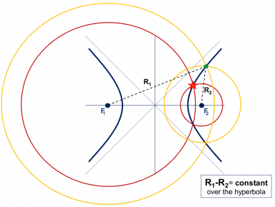
[[File: | [[File:Unknown Offset.png|none|thumb|400px|'''''Figure 1.2:''''' An (unknown) o�set dt in the ship's clock produces a shift in the measured ranges (Ri = �i + dt) (or pseudoranges), varying the circumference radius. But, as both pseudoranges R1 and R2 have been measured with the same clock, this o�set cancels on the di�fference of ranges R1 R2 = �1 �2 = ctt. Thence, the ship is located at a branch of the hyperbola R1 R2 = ctt.]] | ||
[[Category:Fundamentals]] | [[Category:Fundamentals]] | ||
Revision as of 21:17, 4 January 2011
The basic observable in a GNSS system is the time required for a signal to travel from the satellite (transmitter) to the receiver. This travelling time, multiplied by the speed of light, provides a measure of the apparent distance (pseudo range) between them. The following example summarises, for a two-dimensional case, the basic ideas involved in the GNSS positioning:
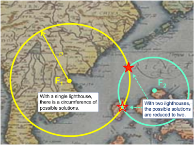
Let's suppose that a lighthouse is emitting acoustic signals at regular intervals of 10 minutes and intense enough to be heard some kilometres away. Let's also assume a ship with a clock perfectly synchronised with the one in the lighthouse, receiving these signals at a time not being an exact multiple of 10 minutes, for example, 20 seconds later [math]\displaystyle{ \left (t = n * 10^m + 20^s \right) }[/math] These 20 seconds will correspond to the propagation time of sound from the lighthouse (transmitter) to the ship (receiver). The distance ρ between them can be obtained multiplying this value by the speed of sound [math]\displaystyle{ v \simeq 335 m/s }[/math]. That is, ρ = 20 s * 335 m/s = 6.7 km. Obviously, with a single lighthouse it is only possible to determine a single measure of distance. So, the ship could be at any point over a circle of radius ρ, see figure 1.1.
With a second lighthouse, the ship position will be given by the intersection of the two circumferences centred in the two lighthouses and radius determined by their distances to the ship (measured using the acoustic signals). In this case, the ship could be situated at any of the two points of intersection shown in figure 1.1. A third lighthouse will solve the previous ambiguity, nevertheless a rough knowledge of the ship position may allow us to proceed without the third lighthouse. For instance, in figure 1.1, one of the solutions falls on the ground (on an island).
A deeper analysis of a 2-D pseudorange based positioning
Right now, a perfect synchronism between lighthouses and ship clocks has been assumed, but in fact this is very difficult to assure. Notice that a synchronism error between these clocks will produce an erroneous measure of signal propagation time (because it is linked to such clocks) and, in consequence, an error in the range measurements. Let's assume that the ship clock is biased by an o�ffset d� regarding the lighthouses clocks (which are supposed to be fully synchronised). Thence, the measured ranges, R1 and R2, will be shifted by an amount dt = v:d� :
R1 = �1 + dt , R2 = �2 + dt (1.1)
That is, the radius of the circles of �figure 1.1 will vary by an unknown amount dt, see �gure 1.2. From hereafter we will call Ri as pseudorange, because it contains an unknown error dt. At fi�rst glance, it might seem that the intersection of these circles (with an unde�fined radius Ri) could reach any point on the plane (for an arbitrary dt value). However, they will only intersect on the branches of a hyperbola, whose foci are located at the two lighthouses, see fi�gure 1.2. Indeed, as the clock o�ffset dt cancels when differencing the pseudoranges, the possible ship locations must verify the following equation (which de�fines an hyperbola, see �figure 1.2):

