If you wish to contribute or participate in the discussions about articles you are invited to contact the Editor
Tracking Loops
| Receivers | |
|---|---|
| Title | Tracking Loops |
| Author(s) | GMV |
| Level | Advanced |
| Year of Publication | 2011 |
GNSS receivers’ goal is to synchronize a local replica of the transmitted PRN Code with the incoming signal, in order to estimate the distance travelled by the incoming signal as accurately as possible. For that purpose, tracking loops are used in a closed loop to follow continuously the code and carrier parameters of the incoming signal. These loops are often designated as code and carrier tracking loops.
Block Diagram
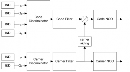
In order to extract information from the incoming signals, GNSS receivers track them by replicating the PRN code and adjusting its code delay and carrier phase continuously so as to guarantee synchronization with the incoming signal. In its most common implementation, the receiver implements code and carrier tracking loops to achieve synchronization with the incoming signal, as depicted in Figure 1.
The tracking loops include:
- Integrate & Dump (I&D): blocks that accumulate the correlators’ outputs, and provide their In-phase I and Quadrature Q components.
- Discriminators: process the correlators’ outputs to provide measurable quantities (e.g. carrier phase information).
- Filters: filter the discriminators’ outputs to reduce noise.
- NCO: Numerical Control Oscillators convert the filter outputs into usable correction factors of Doppler frequency and code delay, which are fed back to the Doppler removal and Local code Generators blocks respectively, as shown here.
While code tracking loops follow the code delay of the incoming signal using Delay Lock Loops (DLL), carrier tracking loops can be designed to follow either the phase of the incoming signal – using Phase Lock Loops (PLL), or the Doppler frequency of the incoming signal using Frequency Lock Loops (FLL). Nevertheless, receivers may implement both FLLs and PLLs: this decision, together with the dimensioning of all the components within the tracking loops, is part of a series of trade-offs conducted during receiver design.
As an example, the selection of the integration times used in I&D blocks (also discussed here) is a trade-off between accuracy and robustness to receiver dynamics. On one hand, the longer the integration time, the less noise is expected at the correlators’ outputs; on the other hand, shorter integration times are more robust in high dynamic stress signal conditions.
Loop Filters
The objective of the loop filters is to filter the discriminator output in order to reduce noise. These measurements are fed to the loop's NCOs that subtract them from the original input signal to produce a correction factor. This correction is then fed back into the first blocks of the receiver channels, namely Doppler removal and local replica generator, so as to update the current estimations.
The design of the loop filters consists in dimensioning the filter order and bandwidth, in order to determine its response to the signal dynamics. In general, the design of the filter noise bandwidth [math]\displaystyle{ B_n\, }[/math] needs to consider the integration time [math]\displaystyle{ T\, }[/math], so that:
[math]\displaystyle{ B_nT \lt \lt 1\, }[/math]
Whenever this condition is not guaranteed, the actual bandwidth tends to be larger than the desired one, leading to filter instability.
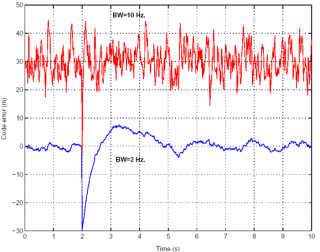
The effect of the filter noise bandwidth is illustrated in Figure 2, which depicts the filter response to a phase step. It can be seen on one hand, that lower bandwidths present less noisy results (since they correspond to longer integration times), and on the other hand, higher bandwidths have faster response times.
In terms of filter order considerations, the higher the order, the better the capability of the filter to follow the LOS dynamics. As such:
- 1st order filters are sensitive to velocity stress.
- 2nd order filters are sensitive to acceleration stress.
- 3rd order filters are sensitive to jerk stress.
As a consequence, higher order filters perform better in dynamic stress conditions and provide less noisy results. The drawback relies mainly on the additional computational burden of the filters, since the order of the filter is directly related to the amount of operations. Furthermore, the order also imposes a limit on the filter bandwidth: as an example, a 3rd order filter requires a noise bandwidth below 18 Hz in order to guarantee stability[1].
Aiding
Noting that the carrier loop jitter is much less noisy than the code loop jitter, it is possible to use the measurements from the carrier loop to remove the LOS (Line-Of-Sight) dynamics of the code loop, with the advantage of being able to lower the order of the code loop filter, as well as its bandwidth. This architecture is often called carrier-aiding, since it allows having a 3rd order PLL filter feeding its information to a 2nd order DLL filter, maintaining the same levels of performance of an unaided 3rd order DLL filter, as shown in Figure 1. For that purpose, a scale factor needs to be applied to the carrier filter outputs before including them in the code loop, in order to account for the fact that the Doppler effect on the signal is inversely proportional to its wavelength[1]:
[math]\displaystyle{ SF=\frac{R_c}{f_L}\, }[/math]
where:
- [math]\displaystyle{ R_c\, }[/math] is the code chipping rate of the signal at hand.
- [math]\displaystyle{ f_L\, }[/math] is the carrier frequency of the signal at hand.
Another way to remove higher order dynamics from the loops is to use external inertial sensors; this approach also allows for lower filter orders in the tracking loops[2].
Vector Processing
In conventional receivers, tracking loops - namely Delay Lock Loops (DLL) operate independently, as they are assigned to dedicated channels to provide observables, e.g. pseudorange information for the case of the DLL.
The concept of Vector DLL (VDLL) relies on the fact that pseudo-range is not an observable per se[3]. Instead, the receiver observes the sum of signals coming from different satellites. Therefore it is possible to close the loop of the solution computation back to the signal correlation outputs, which are the actual measured quantities.
As an example, vector processing techniques have been used to estimate Doppler measurements from different satellites, and feeding back this information in order to be able to reduce the PLL filter bandwidth [4]. Vector processing may reduce the noise from all channels and guarantee that the loop bandwidth is now driven by the receiver dynamics. Furthermore, the VDLL may be able to cope with the blockage of one single satellite, as long as enough (strong) satellites are visible. The actual effect on the system is equivalent to the increase of noise on the remaining channels.
Conversely, a potential disadvantage of the vector processing is contamination among the measurements, e.g. in strong multipath environments such as urban canyons.
Related articles
- Generic Receiver Description
- Phase Lock Loop (PLL)
- Frequency Lock Loop (FLL)
- Delay Lock Loop (DLL)
- System Design Details
- Baseband Processing
References
- ^ a b Kaplan E.D., Hegarty C.J.,"Understanding GPS: Principles and Applications", second edition.
- ^ ”Development of INS-Aided GPS Tracking Loop and Flight Test Evaluation”, Toshiaki Tsujii1, Takeshi Fujiwara, Yoshimitsu Suganuma, Hiroshi Tomita,and Ivan Petrovski, Aviation Program Group, Japan Aerospace Exploration Agency, iP-Solutions, Tokyo, Japan.
- ^ J. J. Spilker Jr., “Global Positioning System: Theory and Applications”, Volume I, Chapter Fundamentals of Signal Tracking Theory, edited by B. Parkinson and J. Spilker Jr, Published by the American Institute of Aeronautcs and Astronautics, Inc
- ^ Chiou, Tsung-Yu, Seo, Jiwon, Walter, Todd, Enge, Per, "Performance of a Doppler-Aided GPS Navigation System for Aviation Applications under Ionospheric Scintillation," Proceedings of the 21st International Technical Meeting of the Satellite Division of The Institute of Navigation (ION GNSS 2008), Savannah, GA, September 2008, pp. 1139-1147.


