If you wish to contribute or participate in the discussions about articles you are invited to contact the Editor
Multicorrelator
| Receivers | |
|---|---|
| Title | Multicorrelator |
| Author(s) | GMV |
| Level | Advanced |
| Year of Publication | 2011 |
It is commonly said that correlation is the key operation in the GNSS receiver in order to achieve synchronization with the incoming signals from each satellite. However, a single correlator is not enough to fulfill this purpose; in fact, even the simplest GNSS receiver supports multi-correlators to achieve synchronization and/ or to improve the accuracy of the generated observables.
Concept
The basic concept within the baseband processing of a GNSS receiver relies in correlating the incoming signal with a local replica of the PRN code (also called ranging code) in order to derive estimates of the Doppler frequency and the code delay (from which to shift the local replica) that guarantee that it is aligned with the incoming signal. The aligned replica is often called Prompt (P) correlator - also discussed here.
In reality, even the simplest GNSS receiver supports at least three correlators:
- Prompt: an aligned replica with the incoming signal
- Early: a replica that is shifted earlier in time than the prompt replica
- Late: a replica that is shifted later in time than the prompt replica
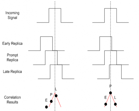
Figure 1 depicts an example of the outputs of these correlators when the prompt correlator is completely aligned with the incoming signal (which is the desired situation) and when synchronization has not yet been achieved.
The correlation results are points over the autocorrelation function – in this example, it is a triangular function accounting for BPSK modulation used, for example in GPS L1 C/A.
From inspection of the figure, the following comments can be intuitively derived:
- When the signal is correctly tracked:
- The power of the prompt correlator is higher than the power of the Early and Late correlators
- The E and L correlators have comparable powers
- When the signal is not correctly tracked, it is possible by analysis of the powers of the E, P, L correlators to “have an idea” as to how the replicas should be delayed to correct for this. For example, in the left hand picture one can see that the code delay should be corrected so as to shift all three replicas towards the right hand side. This is actually the objective of the Tracking Loops.
- The spacing between the Early and Late correlators, also referred to as E-L spacing, is an important parameter in the receiver
- It should be lower than 2 chips (otherwise it falls out of the auto-correlation function)
- If it is too small (e.g. near zero), it will not be so easy to distinguish the correlators, especially in noisy conditions
- Smaller E-L spacings tend to provide more robust navigation, since they render the correlators’ outputs insensitive to potential distortions of the autocorrelation outside that region.
These concepts are further explored here.
Block Diagram
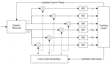
Figure 2 depicts the baseband processing block diagram for a single channel, with focus on the correlators.
This representation shows how the correlators’ outputs (both the real and the imaginary part, i.e. using the In-phase and Quadrature component of the incoming signal respectively) are computed. These outputs are then used by the Tracking Loops to compute new estimates of:
- The code delay: additional delay that should be used to adjust the local code replicas
- The Doppler frequency: adjustment of the Doppler removal block
This is an iterative process that the receiver supports continuously. The Integrate and Dump (I&D) blocks are used to integrate the correlation outputs over time, either coherently or non-coherently, as discussed here.
In parallel, lock detectors use these correlators’ outputs to assess whether or not the incoming signal is actually being tracked. This is justified by the fact that, in noisy conditions, the tracking loops may diverge from the real peak or that a false acquisition may occur.
Mathematical Model
Neglecting noise and picking up from Baseband Processing, the Prompt correlator output can be written as:
[math]\displaystyle{ I_P = Ad R_{x} (\tau_e) cos(\phi_e) }[/math]
[math]\displaystyle{ Q_P = -AdR_{x}(\tau_e)sin(\phi_e) }[/math]
The expressions for the Early and Late replicas are given by:
[math]\displaystyle{ I_E = Ad R_{x} (\tau_e-\frac{\delta}{2}) cos(\phi_e) }[/math]
[math]\displaystyle{ Q_E = -AdR_{x}(\tau_e-\frac{\delta}{2})sin(\phi_e) }[/math]
[math]\displaystyle{ I_L = Ad R_{x} (\tau_e+\frac{\delta}{2}) cos(\phi_e) }[/math]
[math]\displaystyle{ Q_L = -AdR_{x}(\tau_e+\frac{\delta}{2})sin(\phi_e) }[/math]
- [math]\displaystyle{ \tau_e }[/math] is the error of the code delay estimated at the receiver
- [math]\displaystyle{ \phi_e }[/math] is the error of the carrier phase estimated at the receiver
- E, P, L indexes stand for Early, Prompt and Late respectively
- [math]\displaystyle{ \delta }[/math] is the Early-Late spacing
Please note that the phase error can also be written as:
[math]\displaystyle{ \phi_e = 2\pi f_e t + \phi_0 }[/math]
where
- [math]\displaystyle{ f_e }[/math] is the error of the estimated Doppler frequency (and receiver clock instabilities) at the receiver
- [math]\displaystyle{ \phi_0 }[/math] is the initial incoming signal phase
Further Applications
Although the basic receivers use three correlators to track the incoming signal, one can imagine that the number of correlators could be increased (at the cost of power and resources consumption, of course) in order to extract further information. These kind of techniques are actually used in advanced signal processing receivers to achieve higher performances.
Two examples are:
- Multipath Mitigation
The Multipath Estimating Delay Lock Loop (MEDLL) was first proposed in 1992 by Van Nee[1]. The MEDLL estimates the amplitude, delay and phase of each multipath component using maximum likelihood criteria. The contribution to the correlation function is in turn subtracted from the measured correlation function. When this process is complete, the estimate of the direct path correlation function is left. Finally, a standard E-L DLL is applied in order to estimate optimally the code loop tracking error[2]. In practice, 10 or more correlators are employed in order to increase the resolution of the correlation function obtained by sampling
- Tracking of BOC modulations
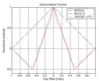
The bump jumping algorithm proposed in [3] is designed to track the BOC modulated signals. In fact, the autocorrelation function of the BOC signals presents more than one peak, as illustrated in Figure 3, leading to several zero crossings of the discriminator response. Thus, the receiver needs to implement a mechanism that ensures it is tracking the correct autocorrelation peak. The bump jumping mechanism consists in adding two extra correlators to the receiver tracking loops structure: the very early (VE) and the very late (VL) correlators.
Related articles
References
- ^ R. Van Nee, “The Multipath Estimating Delay Lock Loop”, IEEE ISSSTA 92, 1992, Japan, pp 39-42
- ^ B. Townsend, P. Fenton, K. Van Dierondonck, R.Van Nee, “Performance Evaluation of the Multipath Estimating Lock Loop”, ION Navigation, VOL. 42, No. 3, fall 1995,pp 503-514
- ^ P. Fine, W. Wilson, “Tracking Algorithm for GPS Offset Carrier Signals,” ION NTM 1999, San Diego, MA, pp. 671-676


