If you wish to contribute or participate in the discussions about articles you are invited to contact the Editor
Frequency Lock Loop (FLL)
| Receivers | |
|---|---|
| Title | Frequency Lock Loop (FLL) |
| Author(s) | GMV |
| Level | Advanced |
| Year of Publication | 2011 |
Frequency Lock Loops are part of the Tracking Loops and aim at tracking the frequency of the incoming GNSS signal, providing corrections in a continuous loop.
Principle
Frequency Lock Loops (FLL) track the Doppler frequency of the incoming signal (with respect to Intermediate Frequency), without necessarily correcting for phase. For that purpose, the PLL uses integrations, filters and Numerical Control Oscillators (NCO) – described here – as any other loop. The specificity relies on the discriminator used to assess the current phase error estimated at the receiver.
The principle behind the FLL is to retrieve frequency information by using the derivative of the phase between two consecutive samples.
The FLL is expected to work well if the coherent integration time, T, is small, in order to avoid aliasing:
[math]\displaystyle{ \frac{-1}{2T}\lt \hat {f}\lt \frac{1}{2T} }[/math]
Discriminators
Defining cross and dot product as:
[math]\displaystyle{ cross=I_{P1} \times Q_{P2} - I_{P2} \times Q_{P1} }[/math]
[math]\displaystyle{ dot=I_{P1} \times I_{P2} + Q_{P1} \times Q_{P2} }[/math]
where the indexes 1 and 2 refer to samples taken at consecutive time instants: [math]\displaystyle{ t_1 }[/math] and [math]\displaystyle{ t_2 }[/math].
Then the most commonly used FLL discriminators are (ordered by computational burden) [1]:
- [math]\displaystyle{ \frac{cross}{t_2-t_1} }[/math]
- [math]\displaystyle{ \frac{cross \times sign(dot)}{t_2-t_1} }[/math]
- [math]\displaystyle{ \frac{ATAN2 (cross, dot)}{t_2-t_1} }[/math]
The ATAN2 discriminator is optimal although it has the greater computational requirements. Finally, the FLL is insensitive to data transitions as long as the consecutive measurements (correlator outputs) refer to the same data bit.
Performance
The main sources of errors in the FLL are frequency jitter and dynamic stress error [1], which are greatly produced by thermal noise. The FLL thermal noise jitter can be written (in m/s) as:
[math]\displaystyle{ \sigma_{th}=\frac{\lambda}{2 \pi T} \sqrt{\frac{4FB_n}{C/N_0}(1+\frac{1}{TC/N_0})} }[/math]
Where
- [math]\displaystyle{ \lambda }[/math] is wavelength of the carrier signal [m]
- [math]\displaystyle{ B_n }[/math] is the loop bandwidth [Hz]
- [math]\displaystyle{ C/N_0 }[/math] is the carrier to noise ratio [dB-Hz]
- T is the integration time [s]
- F=1 at high carrier to noise ration and 2 otherwise
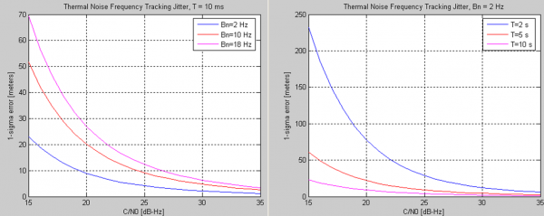
The performance of the FLL depends mainly on the loop bandwidth and the integration times used to accumulate the correlator outputs.
The impact of these parameters is shown in Figure 1, and they are visible mainly for low carrier to noise ratio.
These results also illustrate the fact that longer integration times (and lower bandwidths) lead to noise reduction and hence higher performances, as discussed previously.
In addition, lower loop noise bandwidths allow coping with higher dynamic environments.
Related articles
- Generic Receiver Description
- Baseband Processing
- Digital Signal Processing
- Tracking Loops
- Phase Lock Loop (PLL)
- Delay Lock Loop (DLL)

