If you wish to contribute or participate in the discussions about articles you are invited to contact the Editor
Phase Lock Loop (PLL)
| Receivers | |
|---|---|
| Title | Phase Lock Loop (PLL) |
| Edited by | GMV |
| Level | Advanced |
| Year of Publication | 2011 |
Phase Lock Loops are part of the receiver's signal tracking loops, and aim at tracking the phase of the incoming GNSS signal. The PLL provides a correction of the phase in a continuous loop, generating a phase error signal.
Principle
The Phase Lock Loop (PLL) tracks and estimates the current misalignment between the Prompt correlator and the incoming signal phase, within the tracking loops. For that purpose, the PLL uses integrations, filters and Numerical Control Oscillators (NCO) – described here – as any other typical loop. In this case, the specificity relies on the discriminator used to assess the current phase error estimated at the receiver.
As elaborated here, the output of the correlation and accumulation blocks can be written in its In-phase (I) and Quadrature (Q) components as:
[math]\displaystyle{ I_P = A_X d_X R_X (\tau_e) cos(\phi_e)\, }[/math]
[math]\displaystyle{ Q_P = -A_X d_X R_X (\tau_e)sin(\phi_e)\, }[/math]
where:
- [math]\displaystyle{ R_X\, }[/math] is the auto-correlation of the X PRN code.
- [math]\displaystyle{ P\, }[/math] stands for the Prompt replica, i.e. the replica generated at the receiver which is aligned with the incoming signal.
- [math]\displaystyle{ \tau_e\, }[/math] is the error of the code delay estimated at the receiver.
- [math]\displaystyle{ \phi_e\, }[/math] is the error of the carrier phase estimated at the receiver.
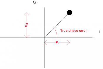
Figure 1 represents the output of the In-phase and Quadrature components of the prompt correlator. When tracking the signal correctly, the prompt vector should be, ideally, in the In-phase axis (with no Quadrature component). Therefore, the phase error can be retrieved from the phase of the correlator using [math]\displaystyle{ P_I\, }[/math] and [math]\displaystyle{ P_Q\, }[/math], and the PLL will feedback a new carrier correction in order to minimize this error.
Discriminators
Two types of PLL discriminators are often mentioned[1]:
- Sensitive to bit transitions, hence phase shifts:
The most common discriminator sensitive to bit transitions is given by:
[math]\displaystyle{ \phi_e =ATAN2(Q_P,I_P)\, }[/math]
which is optimal, but presents a high computational burden. In order to use such discriminator, the receiver must ensure that the inputs do not include bit transitions, e.g. doing data wipe-off during the integration.
- Insensitive to bit transitions, also called Costas loop:
The classic Costas loop discriminator (the near optimal) can be written as:
[math]\displaystyle{ sin(2\phi_e) =Q_P \times I_P\, }[/math]
and another example of Costas loops is given by:
[math]\displaystyle{ tan(\phi_e) =Q_P / I_P\, }[/math]
The choice of the discriminator is a trade-off between performance of the PLL and required hardware resources, as well as complexity.
Performance
The main sources of errors in the PLL are phase jitter and dynamic stress error[1], which are mainly produced by thermal noise. The PLL thermal noise jitter for an arctangent PLL can be written (in meters) as:
[math]\displaystyle{ \sigma_{th}=\frac{\lambda}{2 \pi} \sqrt{\frac{B_n}{C/N_0}(1+\frac{1}{2TC/N_0})}\, }[/math]
where:
- [math]\displaystyle{ \lambda\, }[/math] is wavelength of the carrier signal [m].
- [math]\displaystyle{ B_n\, }[/math] is the loop bandwidth [Hz].
- [math]\displaystyle{ C/N_0\, }[/math] is the carrier to noise ratio [dB-Hz].
- [math]\displaystyle{ T\, }[/math] is the integration time [s].
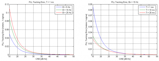
The performance of the PLL depends mainly on the loop bandwidth and the integration times used to accumulate the correlator outputs. The impact of these parameters is shown in Figure 2, and they are visible mainly for low carrier to noise ratio.
These results also illustrate the fact that longer integration times (and lower bandwidths) lead to noise reduction, hence higher performances, as discussed here.
Related articles
- Generic Receiver Description
- Baseband Processing
- Digital Signal Processing
- Tracking Loops
- Delay Lock Loop (DLL)
- Frequency Lock Loop (FLL)


