If you wish to contribute or participate in the discussions about articles you are invited to contact the Editor
Galileo Signal Plan
Galileo E1 Band
The E1 Open Service (OS) modulation receives the name of CBOC (Composite Binary Offset Carrier) and is a particular implementation of MBOC (Multiplexed BOC) [J.-A. Avila-Rodriguez et al., 2007][1]. MBOC(6,1,1/11) is the result of multiplexing a wideband signal – BOC(6,1) – with a narrowband signal – BOC(1,1) – in such a way that 1/11 of the power is allocated, in average, to the high frequency component. This signal was the last one to be defined.
The normalized (unit power) power spectral density, specified without the effect of band-limiting filters and payload imperfections, is given by
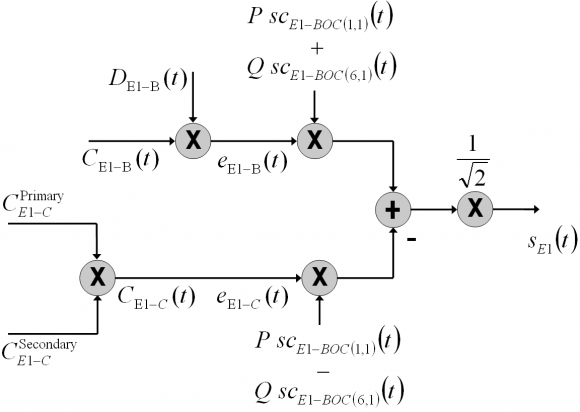
As in [Galileo SIS ICD, 2010] [2], the generic view of the E1 Open Service signal generation can be depicted as follows [J.-A. Avila-Rodriguez et al., 2007][1]:
The whole transmitted Galileo E1 signal consists of the multiplexing of the three following components:
- The E1 Open Service Data channel [math]\displaystyle{ e_{E1-B}(t) }[/math] is generated from the I/NAV navigation data stream [math]\displaystyle{ D_{E1-B}(t) }[/math] and the ranging code [math]\displaystyle{ C_{E1-B}(t) }[/math], which are then modulated with the sub-carriers [math]\displaystyle{ SC_{E1-BOC(1,1)}(t) }[/math] and [math]\displaystyle{ SC_{E1-BOC(6,1)}(t) }[/math] of BOC(1,1) and BOC(6,1) respectively.
- The E1 Open Service Pilot channel [math]\displaystyle{ e_{E1-C}(t) }[/math] is generated from the ranging code [math]\displaystyle{ C_{E1-C}(t) }[/math], including its secondary code, which is then modulated with the sub-carriers [math]\displaystyle{ SC_{E1-BOC(1,1)}(t) }[/math] and [math]\displaystyle{ SC_{E1-BOC(6,1)}(t) }[/math] in anti-phase.
- The E1 PRS channel, also denoted as E1-A, which results from the modulo-two addition (respectively product if we consider the physical bipolar representation of the signal) of the PRS data stream [math]\displaystyle{ D_{PRS}(t) }[/math], the PRS code sequence [math]\displaystyle{ C_{PRS}(t) }[/math] and the sub-carrier [math]\displaystyle{ SC_{PRS}(t) }[/math]. This sub-carrier consists of a BOC(15,2.5) in cosine phasing.
For more details on the mathematical definition of the signal refer to Coherent Adaptive Sub-Carrier Modulation (CASM) and Interplex where it is described more in detail.
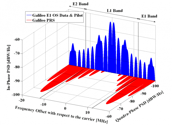
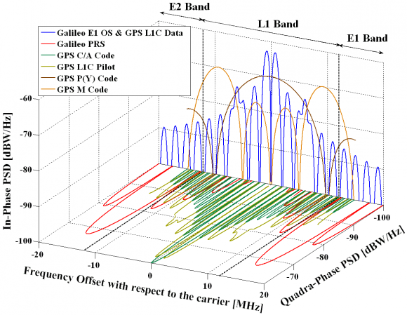
It is interesting to see how the spectra of the two systems described so far in E1/L1 overlap:
It is important to recall that for a long time the actual E1 band received the name of L1 band in analogy with GPS and it was not until the publication of the [Galileo SIS ICD, 2008] [3] that L1 changed to the current E1.
The E1 Open Service (OS) codes are, as well as the E6 CS codes that we will see later, also random memory codes. The plain number of choices to set the 0’s and 1’s for the whole code family is enormous and thus special algorithms have to be applied to generate random codes efficiently [J.-A. Avila-Rodriguez et al., 2007] [1].
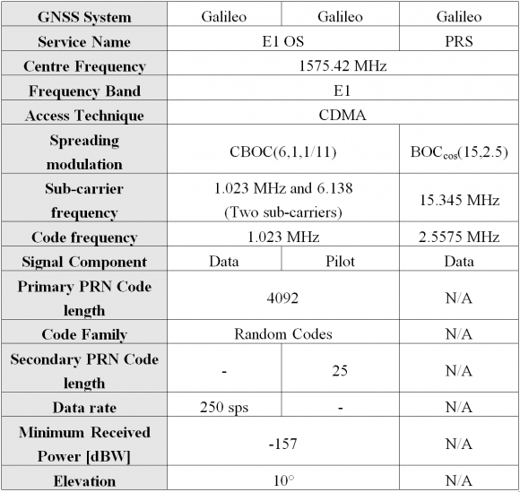
Finally, the technical characteristics of all the Galileo signals in E1 can be summarized in the following table:
Galileo E6 Band
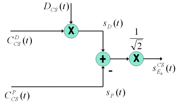
As shown in [Galileo SIS ICD, 2010][2], the transmitted Galileo E6 signal consists of the following three components:
- The E6 Commercial Service (CS) data channel: this modulating signal is the modulo-two addition of the E6 CS navigation data stream [math]\displaystyle{ D_{CS}(t) }[/math] with the CS data channel code sequence [math]\displaystyle{ D_{CS}^D(t) }[/math]. This last one is already modulated by a BPSK(5) at 5.115 MHz.
- The E6 Commercial Service (CS) pilot channel: this modulating signal is the modulo-two addition of the E6 CS pilot channel code [math]\displaystyle{ C_{CS}^P(t) }[/math] with a BPSK(5) at 5.115 MHz.
- Finally, the E6 PRS channel is the modulo-two addition of the E6 PRS navigation data stream [math]\displaystyle{ D_{PRS}(t) }[/math] with the PRS channel code sequence [math]\displaystyle{ C_{PRS}(t) }[/math] at 5.115 MHz. This signal is further modulated by a sub-carrier of 10.23 MHz in cosine phasing.
This is graphically shown as follows:
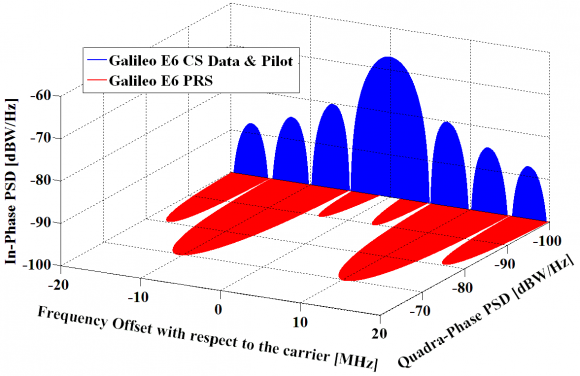
Moreover, the spectrum of the different E6 signals is shown to be as follows:
The E6 Commercial Service (CS) codes are random codes [J. Winkel, 2006] [4]. The main idea behind is to generate a family of codes that fulfils the properties of randomness as well as possible [J.-A. Avila-Rodriguez et al., 2007] [1]. The codes can be driven to fulfil special properties such as balance and weakened balance, where the probability of 0’s and 1’s must not be identical but within a well-defined range, or to realize the autocorrelation side-lobe zero (ASZ) property. This latter property guarantees that the autocorrelation values of every code correlate to zero with a delayed version of itself, shifted by one chip.
Galileo E5 Band
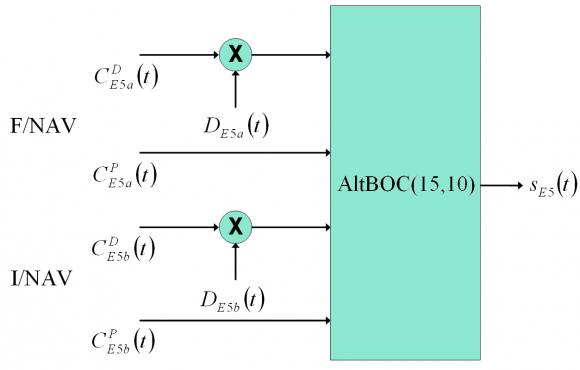
The different Galileo E5 signal components are generated according to the following [Galileo SIS ICD, 2010][2]:
- The E5a data channel: This channel is the modulo-two addition of the E5a navigation data stream [math]\displaystyle{ D_{E5a}(t) }[/math] with the E5a data channel PRN code sequence [math]\displaystyle{ C_{E5a}^D(t) }[/math] of chipping rate 10.23 MHz.
- The E5a pilot channel: This channel is the E5a pilot channel PRN code sequence [math]\displaystyle{ C_{E5a}^P(t) }[/math] of chipping rate 10.23 MHz.
- The E5b data channel: This channel is the modulo-two addition of the E5b navigation data stream [math]\displaystyle{ D_{E5b}(t) }[/math] with the E5b data channel PRN code sequence [math]\displaystyle{ C_{E5b}^D(t) }[/math] of chipping rate 10.23 MHz.
- The E5b pilot channel: This channel is the E5b pilot channel PRN code sequence [math]\displaystyle{ C_{E5b}^P(t) }[/math] of chipping rate 10.23 MHz.
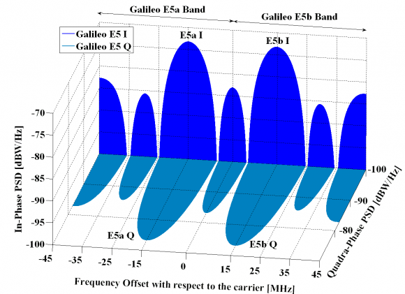
The E5 modulation receives the name of AltBOC and is a modified version of a Binary Offset Carrier (BOC) with code rate of 10.23 MHz and a sub-carrier frequency of 15.345 MHz. AltBOC(15,10) is a wideband signal that is transmitted at 1191.795 MHz. Next figure shows the Galileo E5 signal modulation diagram:
The power spectral density for the modified AltBOC(15,10) modulation with constant envelope is shown to adopt the form:
adopting the spectrum of the E5 signal modulation the following form:
As we can recognize from the figure above, the AltBOC(15,10) modulation is very similar to two BPSK(10) signals shifted by 15 MHz to the left and right of the carrier frequency. Indeed, since to acquire all the main lobes of the modulation a very wide bandwidth is necessary, many receivers will operate correlating the AltBOC signal with a BPSK(10) replica.
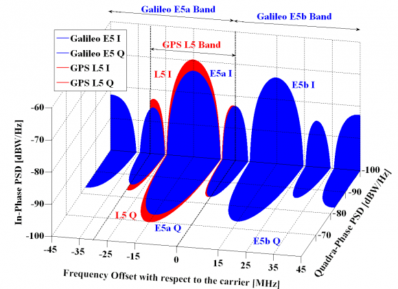
To have a better feeling about the overlapping between GPS and Galileo in E5, the next figure shows all the signals described so far for this band.
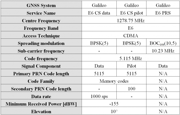
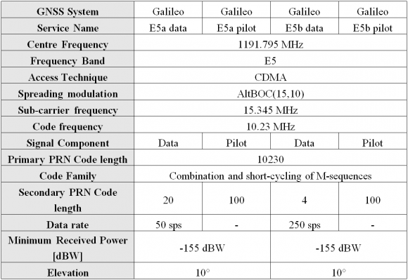
The E5 primary codes can be generated with shift registers. Indeed, the outputs of two parallel registers are modulo-two added to generate the primary codes. For more details on the start values of the primary codes and the corresponding secondary codes of each satellite, refer to [Galileo SIS ICD, 2010][2]. Finally, some details on the technical characteristics of the E5 signal are presented.
Galileo C-band
The Radio-Navigation Satellite Service (RNSS) portion of the RF spectrum is overcrowded. This is especially true on the E1/L1 band. Nevertheless even those bands that have not been used yet will certainly be shared by many systems in the near future. Thus, the search of other free frequency resources is something that will occur with a high probability in the next years.
During the World Radio Conference 2000 (WRC-2000), the Galileo program obtained authorization to use C-band frequencies between 5010 and 5030 MHz. At the time, a dedicated portion of the C-band was assigned for Radio-Navigation, but technical complexities made it impossible for the first generation of Galileo.
Indeed, phase noise problems, the higher free space attenuation (related to the use of omni directional antennae) and the strong signal attenuation due to rain made all the proposed solutions not adequate for the first Galileo constellation. However, in some decades things could have changed and C-band could be a real alternative. As suggested in [G.W. Hein et al., 2007b] [5] and [G.W. Hein et al., 2007c][6], the C-band could be reserved for military/governmental applications leaving the L-band alone for civil users. This would have interesting benefits to both types of user and consequences as depicted in that article.
References
- ^ a b c d [J.-A. Avila-Rodriguez et al., 2007] J.-A. Avila-Rodriguez, G.W. Hein, S. Wallner, J.-L. Issler, L. Ries, L. Lestarquit, A. de Latour, J. Godet, F. Bastide, A.R. Pratt, J.I.R. Owen, M. Falcone, T. Burger, The MBOC Modulation: The Final Touch to the Galileo Frequency and Signal Plan, Proceedings of the International Technical Meeting of the Institute of Navigation, ION-GNSS 2006, 25-28 September, 2006, Fort Worth, Texas, USA.
- ^ a b c d [Galileo SIS ICD, 2010] Galileo Open Service Signal In Space Interface Control Document (OS SIS ICD) Issue 1, Revision 1, 1 September 2010, 2010
- ^ [Galileo SIS ICD, 2008] Galileo Open Service Signal In Space Interface Control Document (OS SIS ICD) Draft 1 01/02/2008, 2008
- ^ [J. Winkel, 2006] J. Winkel, Spreading Codes for a Satellite Navigation System, Patent number WO/2006/063613, International Application No.: PCT/EP2004/014488, Publication date: 22 June 2006
- ^ [G.W. Hein et al., 2007b] G.W. Hein, J.-A. Avila-Rodriguez, S.Wallner, T. Pany, B. Eissfeller and P. Hartl, Envisioning a Future GNSS System of Systems: Part 2, Inside GNSS – Working Papers, Vol. 2, No. 2, March/April 2007, pp. 64-72.
- ^ [G.W. Hein et al., 2007c] G.W. Hein, J.-A. Avila-Rodriguez, S.Wallner, T. Pany, M. Irsigler, B. Eissfeller and P. Hartl, Envisioning a Future GNSS System of Systems: Part 3, Inside GNSS – Working Papers, Vol. 2, No. 4, May/June 2007.
Credits
The information presented in this NAVIPEDIA’s article is an extract of the PhD work performed by Dr. Jose Ángel Ávila Rodríguez in the FAF University of Munich as part of his Doctoral Thesis “On Generalized Signal Waveforms for Satellite Navigation” presented in June 2008, Munich (Germany)
