If you wish to contribute or participate in the discussions about articles you are invited to contact the Editor
Binary Coded Symbols (BCS)
| Fundamentals | |
|---|---|
| Title | Binary Coded Symbols (BCS) |
| Author(s) | J.A Ávila Rodríguez, University FAF Munich, Germany. |
| Level | Advanced |
| Year of Publication | 2011 |
Binary coded symbols are a particular case of Multilevel Coded Spreading Symbols (MCS) signal with a binary chip sequence [math]\displaystyle{ s_l \in \left \{+1,-1\right \} }[/math]. The power spectral density of a generic [math]\displaystyle{ BCS \left ( \left [s_1,s_2,s_3, \cdots ,s_n \right ] \right ),f_c }[/math] can thus be derived from (1) or (2) (see (MCS))
and is shown to adopt the following simplified form:
Or equivalently:
where the first term of the product corresponds to the PSD of a BPSK with [math]\displaystyle{ n f_c }[/math] MHz of chip rate and the second term can be represented by the matrix (see (MCS) for further details)
and is shown to have a power of 1 in an infinite bandwidth. We can thus represent the PSD as follows:
According to this, the function that seems to bring more information about the BCS sequence is the sum of the second factor. This term, namely [math]\displaystyle{ G_Mod (f) }[/math], can be easily computed with the matrix we defined in (5) and we will call it modulation term for short. Furthermore, it is important to realize that the modulation term and the spreading symbol are used indistinctly in the literature to indicate the same.
Furthermore, it is important to note that (6) can be further generalized to
for the case that the sub-chip is modulated by a generic non-rectangular pulse.
The main conclusion that can be drawn from observing this definition matrix is that a subchip alone, or in other words an element of the sequence alone, does not directly affect the PSD of the whole signal. It must be understood in relationship with all the other elements of the sequence. This adds an important complexity. In fact, it is not trivial to derive qualitatively the shape of any generic BCS signal by only having a look at its generation sequence [math]\displaystyle{ \left [ \bar s \right ] = \bar s }[/math].
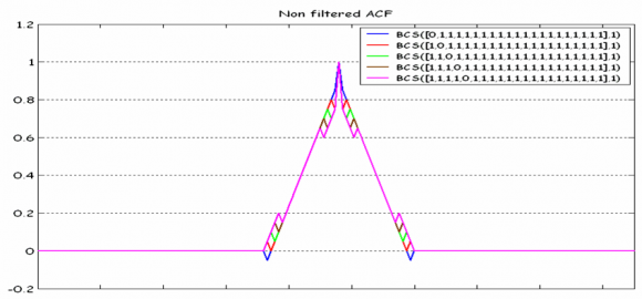
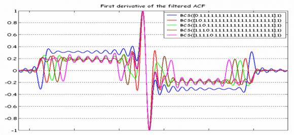
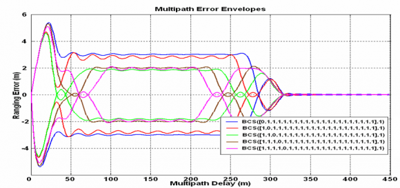
We can clearly see this in the following example. Let us imagine different BCS signals of length 21 consisting only of ones expect for one logical zero (or -1 at signal level) where the zero subchip is placed at different locations within the BCS vector.
For the previous figures, an E-L discriminator with 0.1 chips of spacing was employed. As we can recognize, a single shift to the right in the BCS sequence alters the final multipath performance significantly. This leads us thus to the conclusion that evaluating the multipath performance of a signal with a quick look is not an easy task as it was with BPSK and BOC signals, for example. Even though we knew how the BCS sequence looks like, a simple shift would significantly modify the multipath properties of the signal. Indeed, the mathematical ideas and conclusions gathered above have driven many of the works that were carried out in the past years to find the MBOC signal.
Further information on BCS-related signals can be found in:
References
Credits
The information presented in this NAVIPEDIA’s article is an extract of the PhD work performed by Dr. Jose Ángel Ávila Rodríguez in the FAF University of Munich as part of his Doctoral Thesis “On Generalized Signal Waveforms for Satellite Navigation” presented in June 2008, Munich (Germany)


