If you wish to contribute or participate in the discussions about articles you are invited to contact the Editor
Phase & Group Velocity
| Fundamentals | |
|---|---|
| Title | Phase & Group Velocity |
| Author(s) | J. Sanz Subirana, JM. Juan Zornoza and M. Hernandez-Pajares, University of Catalunia, Spain. |
| Level | Medium |
| Year of Publication | 2011 |
In order to introduce the Phase and Group Velocity definitions, a brief review on wave propagation concepts is given as follows.
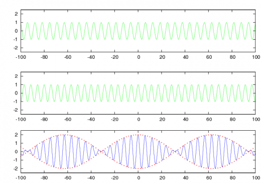
A pure sinusoidal monochromatic signal traveling in the x-direction can be described by (see figure 1 at top):
- [math]\displaystyle{ s(x,t)=s_0\cos(\omega t - k \, x +\phi_0) \qquad\mbox{(1)} }[/math]
where [math]\displaystyle{ \omega=2\pi/T }[/math], [math]\displaystyle{ k=2\pi/\lambda }[/math] and [math]\displaystyle{ T=1/f=2\pi/\omega }[/math], being [math]\displaystyle{ f }[/math], [math]\displaystyle{ T }[/math] and [math]\displaystyle{ \lambda }[/math] the frequency, period and wavelength, respectively.
The [math]\displaystyle{ s(x,t) }[/math] is a function that depends on both time and position. At any fixed instant of time [math]\displaystyle{ t }[/math] the function varies sinusoidally along the [math]\displaystyle{ x }[/math] axis, whereas at any fixed location of the axis [math]\displaystyle{ x }[/math] the function varies sinusoidally with time.
The speed at which the shape is moving, i.e., the speed at which any fixed phase of the cycle is displaced, is called the Phase Velocity. This velocity, according to (1) is given by:
- [math]\displaystyle{ v_{ph}=\frac {\omega}{ k}\qquad\mbox{(2)} }[/math]
because [math]\displaystyle{ \omega t - k x +\phi_0 }[/math] remains constant by changing [math]\displaystyle{ x }[/math] and [math]\displaystyle{ t }[/math] when [math]\displaystyle{ x=\frac{\omega}{ k}\, t }[/math].
An amplitude modulated signal can be generated by simply addition of two sinusoidal signals at slightly different frequencies:
- [math]\displaystyle{ s_1(x,t)=\cos((\omega +\Delta \omega) t - (k+\Delta k) x ), \qquad s_2(x,t)=\cos((\omega -\Delta \omega) t - (k-\Delta k) x ) \qquad\mbox{(3)} }[/math]
Using simple trigonometric identities, it is found:
- [math]\displaystyle{ s_1(x,t)+s_2(x,t)=2\cos(\Delta \omega t - \Delta k \, x)\, \cos(\omega t - k \, x) \qquad\mbox{(4)} }[/math]
A plot with an example to illustrate the combination of signals of equation (4) is shown in figure 1.
From equation (4), it follows that, two signals can appear travelling at two different velocities as a result of the superposition of signals [math]\displaystyle{ s_1(x,t) }[/math] and [math]\displaystyle{ s_2(x,t) }[/math]. That is, in the bottom plot of figure 1, the internal oscillations (in blue) travels at velocity [math]\displaystyle{ v=\frac{\omega}{k} }[/math], whereas the amplitude envelope (in red) travels at velocity [math]\displaystyle{ \frac{\Delta \omega}{\Delta k} }[/math].
The velocity of the modulation [math]\displaystyle{ \frac {\Delta \omega}{\Delta k} }[/math] when considering the limit [math]\displaystyle{ \Delta k \rightarrow 0 }[/math] can be written as:
- [math]\displaystyle{ v_{gr}=\frac {d\omega}{d k}\qquad\mbox{(5)} }[/math]
The equation (5) defines the Group Velocity.
Notice that, when the angular frequency and the wave number [math]\displaystyle{ k }[/math] are proportional, thence the phase and group velocities are the same, i.e. [math]\displaystyle{ v_{gr}=v_{ph} }[/math]. On the other hand, from (2) it is obvious that, in this case, the phase velocity [math]\displaystyle{ v_{ph} }[/math] do not depend on the frequency. A media in which this condition is fulfilled is said to be non-dispersive.
On the contrary, a media which the waves propagation speed varies with the frequency is said to be dispersive (from the dispersion of light by a prism). Thus, the envelope travels at different speed [math]\displaystyle{ v_{gr} }[/math] than the internal oscillations [math]\displaystyle{ v_{ph} }[/math]. In this case, if we were riding along with the envelope in figure 1, we would observe the internal oscillations moving forward from one group to the next.
The refractive index ([math]\displaystyle{ n }[/math]) in a medium is the ratio between the speed propagation of signal in a vacuum ([math]\displaystyle{ c }[/math]) to the speed in the medium ([math]\displaystyle{ v }[/math]), thence, two different refractive indexes can be defined for the group and phase:
- [math]\displaystyle{ n_{ph}=\frac c{v_{ph}}~, \qquad n_{gr}=\frac c{v_{gr}} \qquad\mbox{(6)} }[/math]
In the context of GNSS signals, the carrier waves are propagating with the phase velocity and thence, this is the velocity associated to the carrier measurements. The group velocity is what has to be considered for the code measurements, i.e, pseudoranges obtained from the codes modulated in the carriers [footnotes 1].
As it is explained in the next sections, the troposphere is a non dispersive media for radio waves at the GNSS frequencies. Thence, code and carrier phase measurements are associated to the same velocity in the troposphere. By contrast, codes and phases propagate at different speeds in the ionosphere, resulting in a delay in the code and an advance in the carrier measurements, see Ionospheric Delay.
Notes
- ^ Notice that the information and energy is propagated in a wave as a change in the wave, e.g, by modulating the codes. Thence, the information propagates with the group velocity.

