If you wish to contribute or participate in the discussions about articles you are invited to contact the Editor
EGNOS Space Segment
| EGNOS | |
|---|---|
| Title | EGNOS Space Segment |
| Author(s) | GMV. |
| Level | Basic |
| Year of Publication | 2011 |
The EGNOS space segment is composed by three geostationary satellites centred over Europe:
- Inmarsat-3 AOR-E (Atlantic Ocean Region East) stationed at 15.5° W.
- Inmarsat-3 IOR-W (Indian Ocean Region West) stationed at 25.0°E.
- ESA-Artemis stationed at 21.5° E.
The main criteria followed in the selection of the satellites positions have been:
- Improve the measurement geometry and hence the system availability.
- Maximise the visibility angle diversity and hence minimise the risk of signal blocking.
- Provide dual geostationary coverage (minimum) within the core service area.
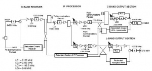
Inmarsat’s Third Generation satellites carry a navigation payload which is used by EGNOS.[1]
The first Inmarsat-3 (F2 AOR-E) satellite carrying an EGNOS transponder was launch in September 2006 (PRN 120) while the second one, Inmarsat-3 F5 IOR-W, was launch in February 1998.[2]
Inmarsat-3s were built by Lockheed Martin Astro Space (now Lockheed Martin Missiles & Space) of the USA, responsible for the basic spacecraft, and the European Matra Marconi Space (now Astrium), which developed the communications payload and the first satellite was launched by Proton launch vehicle.
Inmarsat 3-F5 was the fifth in a series of five third generation satellites. It was launched from the Kourou Space Center aboard an Ariane rocket, it is currently service over the Atlantic Ocean and it could deliver an IERP of up to 48dBW in L-band. Besides, it could dynamically reallocate both RF power and bandwidth among a global beam and five spot beams, allowing greater reuse of the available spectrums.
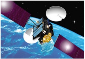
The ESA ARTEMIS satellite is not an ordinary telecommunications satellite. It incorporates new, advanced technologies that expand and improve all areas of navigation, mobile communication and satellite-to-satellite communications. Having reached its final orbital position on 31January 2003, ARTEMIS soon began delivering its planned data-relay, land-mobile and navigation services. In particular, its L-band land mobile payload is being used to complement and augment the European Mobile System, its data-relay payloads are being prepared to provide operational services to ENVISAT and SPOT-4, and its navigation payload a major operational element of the European Global Navigation Overlay Service (EGNOS).[3]
The Artemis navigation payload was introduced at a very late stage of the ARTEMIS satellite development and a very tight schedule was imposed on its procurement. As a consequence and to minimize all possible impacts, it was decided to design it as a completely separated structure, which shall be installed on the spacecraft top floor. Additionally, the payload design and the relevant pieces of equipment were approached, by maximizing the use of already available commercial products and avoiding as much as possible new technologies.
The technical design drivers for the navigation payload were the following:
- Appropriate frequency selection for compatibility with other existing missions;
- Good control of the group delay stability;
- Electrical and mechanical constraints imposed by the existing ARTEMIS hardware;
- Maximum reuse of off-the-shelf equipments for minimum schedule risk.
To ensure maximum compatibility with the existing missions it was decided to select for both the uplink and downlink channels the Ku-band, with a new allocation for the uplink and sharing the LLM channels in the downlink. The selection of a widely spaced Ku-band uplink ensures the possibility to use a very high EIRP in the uplink as required for an interference and jammer robust system.
For the second point, it was decided to limit the number of frequency conversion and to avoid the use of SAW filters selecting a channel filtering at Ku-band. Provisions have been taken to calibrate the payload transit time in temperature. Finally, the channel bandwidth has been slightly oversized to avoid the strong group delay variations at the narrowband channel filter edges.
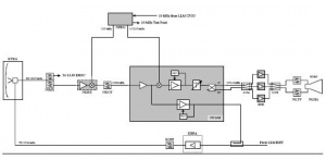
The uplink signal is received at 13.875 GHz by Ku-band feeder link antenna now shared with the LLM payload, and filtered by an input multiplexer which is separating the navigation from the LLM channels. The input multiplexer provides also a first wideband filtering function to reduce interferences.
In the Ku-band receiver the signal is first amplified by a low noise front end and then directly down converted to the Ku-band downlink frequency. In order to maximize the reuse of existing hardware, it has been chosen not to employ a dedicated reference generator for the navigation payload. The same Ultra Stable Oscillator of the LLM payload is used to drive a dedicated frequency generation unit for the required Local Oscillator tones.
The signal is then fed into the narrowband channel filter which is approximately 9 MHZ wide and which is responsible of the principal filtering function of the transponder. The performance of this filter has been specified in order to meet the extremely demanding stability of the payload group delay.
At the output of the channel filter, the signal is fed into the channel amplifier where it is split in two streams. The first, at Ku-band is amplified and fed into the LLM output power stage, while the second is down converted into the GPS L1 frequency (1575.42 MHZ). Normal mode of operation of the channel amplifier is the Automatic Level Control (ALC) mode, which provides a constant output level to the following RF power sections. In ALC mode the navigation payload can provide a stable output level selectable by telecommand, implementing two basic functions:
- Up-link path signal variation recovery.
- L1 channel EIRP selection.
As the EGNOS signal is specified to be transmitted in (right hand) circular polarization, this has been implemented with an output hybrid, which splits the signal into two streams 90° phased apart. These two streams are then driven into the L-band power amplifiers, which are providing 16 W RF e.o.l. with 50 W power consumption, and then fed into the two linear polarization probes of an axially corrugated horn which provides 15 dBi e.o.c. gain.
All units are redounded in order to meet the specified mission probability target of 0.7 of meeting full performance requirements for 10 years on-station life (inclusive of spacecraft). The total mass for the navigation payload, including the structure, the thermal control hardware and the DC harness is 25 kg. Its total power consumption is in the order of 110 W.
GEO Replenishment options
In the frame of future evolutions for the EGNOS Space Segment, the following three options were identified for the EGNOS GEO replenishment:[4]
- Next Generation of Inmarsat Satellites
- Piggy Back Navigation Payload in a planned GEO multi-mission satellite
- In the context of integration of EGNOS into Galileo, the implementation of GALILEO GEOs providing EGNOS links.
Notes
References
- ^ EGNOS Programme Evolution (EGNOS Portal)
- ^ EGNOS GEO Replenishment: Planning for the Future; Javier Ventura-Traveset, European Space Agency; Sally Basker, SBAS Limited; Ken Ashton, National Air Traffic Service Ltd.


