If you wish to contribute or participate in the discussions about articles you are invited to contact the Editor
GPS Time and Frequency Transfer Techniques
| Fundamentals | |
|---|---|
| Title | GPS Time and Frequency Transfer Techniques |
| Author(s) | F. Martín Porqueras. Technical University of Catalonia, Spain |
| Level | Basic |
| Year of Publication | 2012 |
GPS Time and Frequency Transfer Techniques
One-Way Mode
The one-way GPS technique uses the signals obtained from a GPS receiver as the reference for a calibration. The GPS signals are used in real time to synchronize his local clock and GPS time or UTC(USNO). The purpose of the measurement is usually either to synchronize an on-time pulse, or to calibrate a frequency source. To make use of this knowledge, the receiver must then generate a timed output signal (see Synchronization signals provided by a GPS receiver).
Before a receiver is used for measurements, it must complete its signal acquisition process. Part of the acquisition process involves surveying the antenna position. Unlike GPS navigation receivers, which compute position fixes while moving (often at a rate faster than one position fix per second), GPS time and frequency receivers normally do not move at all and do not need to compute position fixes once the survey is completed.
Therefore, time and frequency receivers generally store a single position fix, and use that same position from then on. Many receivers automatically start a survey when they are turned on. When the process is finished, a front panel indicator tells the operator that the receiver is ready to use.
Once the signal acquisition is completed, an output signal from the receiver is connected to a measurement system. For time synchronization measurements, a 1 pps signal from the receiver is generally used as an input to a time interval counter. For frequency measurements, a frequency output (10 MHz, for example, see Figure 1 for stability performances) from a GPSDO is used as an input to a phase comparator, or used as the external time base for a frequency counter.
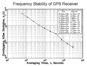 Figure 1: Frequency stability (Allan deviation) of GPS receiver after S/A was set to 0 [1].
Since the GPS satellites transmit signals that are steered to UTC, the long-term accuracy of a GPS receiver has always been excellent. The performance of C/A code receivers became even better on May 2, 2000 (MJD 51666) when the USDOD set Selective Availability (S/A) to zero (refer to GPS Services). Figure 2 is a phase plot showing data from a typical GPS receiver, recorded in the days immediately before and after S/A was set to zero.
 Figure 2: Phase plot showing GPS performance before and after SA was set to zero [1].
Common View Mode
The common-view method is a simple but elegant way to compare two clocks or oscillators located in different places. Unlike one-way measurements that compare a clock or oscillator to GPS, a common-view measurement compares two clocks or oscillators to each other.
Figure 3 shows how the common-view technique works. A GPS satellite (S) serves as a single reference transmitter. The two clocks or oscillators being compared (A and B) are measured against two GPS receivers. The satellite is in common view of both receivers, and both simultaneously receive its signals. Each receiver compares the received signal to its local clock and records the data. Receiver A receives the signal over the path [math]\displaystyle{ \tau_{SA} }[/math] and compares the reference to the local clock (S - Clock A). Receiver B receives the signal over the path [math]\displaystyle{ \tau_{SB} }[/math] and records (S - Clock B). The two receivers then exchange and difference the data.
Common-view directly compares two time and frequency standards. Errors from the two paths ([math]\displaystyle{ \tau _{SA} }[/math] and [math]\displaystyle{ \tau _{SB} }[/math]), that are common to the reference, cancel out, including the performance of the satellite clock. The final measurement result is (Clock A - Clock B) - ([math]\displaystyle{ \tau_{SA} }[/math] - [math]\displaystyle{ \tau_{SB} }[/math]).
The advantage of this technique is that it minimizes certain errors that might be present. The satellite clock errors are completely eliminated since they are common in both receivers. Ephemerides errors in the transmitted data and affecting to the computation of the paths [math]\displaystyle{ \tau_{SA} }[/math] and [math]\displaystyle{ \tau_{SB} }[/math] are minimized. However, the main disadvantaged with respect to the one-way mode is that data between the receivers must be exchanged. On the other hand, the mathematics involved in this technique are very simples since they consist only in subtracting the values obtained at each site to obtain the difference between the two clocks at each site.
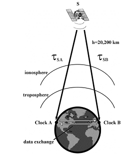 Figure 3: Common view measurement technique [1].
The common-view technique has long been used for international comparisons of time and frequency standards. The international time scales — International Atomic Time (TAI) and Coordinated Universal Time (UTC) — are created by averaging data collected from more than 200 atomic clocks located in about 50 laboratories. Most of these data are collected using common-view GPS measurements. Once the data are sent to the BIPM, the TAI and UTC time scales are computed using a weighted average of all the oscillators. The stability of TAI and UTC is currently about 1 part in [math]\displaystyle{ 10^{15} }[/math] over a period of a few weeks.
The common-view requires a GPS receiver that can read a tracking schedule. This schedule tells the receiver when to start making measurements and which satellite to track. A receiver at another location makes measurements from the same satellite at the same time. The data collected at both sites are then exchanged and compared. Single-channel common-view GPS receivers were first developed at NIST (then the National Bureau of Standards) in 1980. Several companies soon developed similar products based on the NBS/NIST design. Only a few GPS satellites were in orbit during the early 1980’s, and early receivers could track only one satellite at a time. Even though today’s receivers can simultaneously track multiple satellites, the single-channel technique is still widely used for international comparisons.
Multi-channel common-view does not use a schedule. The receiver simply records data from all satellites in view. Although there is more data to process, the multi-channel technique has some obvious advantages. For example, the limited number of tracks makes it impossible for two single-channel users to continuously compare their standards; there will always be gaps in their measurement data. However, if two multi-channel users are located within a reasonable distance of each other (on the same continent, for example), there should always be at least 1 satellite in common-view between them. Therefore, it is often possible for multi-channel users to continuously compare standards with no gaps in their measurement data.
Melting-Pot Mode
The Melting-Pot mode, also known as All in view mode [Petit G. and Jiang Z., 2008][2], can be used to synchronize clocks over widely separated distances. Unlike the Common view mode, the Melting-Pot mode does not require simultaneity in the observations by both stations, it only requires that each station observe as many satellites as possible during the day that its receiver can track.
The individual GPS time versus the local standard's time comparisons are put together over a period of time. The linear fit solution of these points is considered the offset of the GPS time from the local standard's time. Subtracting one local standard's offset time from the other yields the time difference between the two locations.
This method is more robust than the Common View Mode, because it observes significantly more satellites during the day. Therefore, it is more suitable for unattended synchronization systems because the offset values are more stable and the system is more robust to occasional data gaps since the offset is computed from several measurements.
Carrier-Phase Mode
This technique uses both the L1 and L2 carrier frequencies instead of the codes transmitted by the satellites. It is important to note that carrier phase measurements can be one-way measurements made in real-time or post-processed common-view measurements. Since the carrier frequency is more than 1000 times higher than the C/A code frequency, the potential resolution is much higher [Lombardi M. et al., 2001][1].
The phase difference between the satellite oscillator and the receiver’s local oscillator is computed. However, the phase observable is an ambiguous observable, the phase is measured modulo [math]\displaystyle{ 2\pi }[/math] and only the fractional phase can be measured, whereas the pseudorange is an absolute observable. The absolute offset between the remote clocks is then only determined by the code information, while the carrier phases allow to give a precise signal evolution. The use of the pseudorange information together to the carrier phase information increases the accuracy up to a factor 1000.
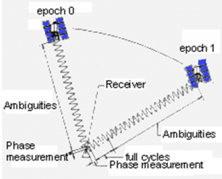 Figure 4: Diagram of the phase measurement [1].
Since the carrier-phase GPS technique requires geodetic GPS receivers as well as making corrections of the collected data using orbital, ionosphere and troposphere models and extensive post-processing, it is not practical to use for everyday measurements. However, the technique is used for experimental purposes and for international comparisons between primary frequency standards when the goal is to reduce the measurement uncertainty as much as possible.
Comparison of the methods
Among the methods presented, the one-way mode is the most extended GPS time transfer method since only one GPS receiver is needed. Although it is the method that presents the worst performances for time and frequency transfer (see Table 1), it is simplicity makes it the real solution for most of the general applications.
For laboratory applications, the accuracy obtained with the one-way mode is not sufficient and one of the other techniques is required to achieve the requirements.
 Table 1: Typical Uncertainties of GPS Measurement Techniques [1].
The common view and melting-pot methods provide better results than the one-way mode by including a limited amount of calculations and the exchange of information between the clocks to be synchronized. The exchange of timing information between the two clocks allows to cancel out the common errors in the time computation of each clock that cannot be minimized in the one-way mode.
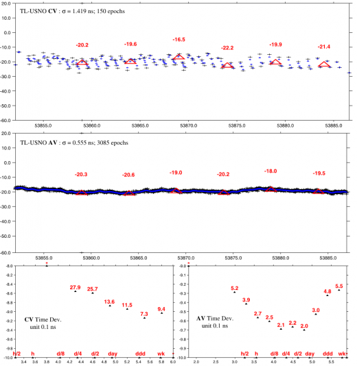 Figure 5: Very long distance time link between TL (Chinese Taipei) and USNO (USA) over May 2006, computed with common view (CV) and Melting-pot (AV). The top two plots show the link values in nanoseconds with statistics. The two plots at the bottom show the corresponding time deviation values, expressed in units of 100 ps. Note that the vertical scale of the two bottom plots is not the same [2].
Between the common view and Melting-pot mode, the latter have the advantages of the common view plus the possibility to work even if there is no common source. For improving the time transfer performances with respect to the one-way mode, the common view mode exploits that most of the errors are common between the time estimation of the two clocks, so the errors will be cancelled by the subtraction of the time measurements of the clocks of each laboratory. On the other hand, the melting pot reduces the errors by means of using as much as measurements are available.
Therefore, for very short baselines where clock measurements share most of the errors (similar paths and geometry to the satellite, same ionosphere delay…) both methods provide similar results, and probably common view provides better results. However, for long baselines where the errors are not common (different path, geometry and ionosphere delay to the satellite), the errors cannot be cancel out by the common view, and the best solution is the melting-pot which tries to reduce the inaccuracies by means of the statistics computation over all the available measurements. Figure 5 shows the time transfer performances for a very long baseline. Clearly, the melting-pot method obtains much better results than the common view mode because the melting-pot uses 20 times more measurements for noise reduction than the common view.
The most accuracy demanding applications use the carrier-phase mode. This mode is not a real time transfer technique, but a method to extract the timing information from the GPS signal. In general, it is assumed that the timing information of the GPS signal is extracted from the C/A code (1 MHz signal). However, the extraction of the timing information from the carrier signal (1.575 GHz) provides up to 1000 times better accuracy than from the C/A code. This technique requires significant post-processing with respect to the other time transfer methods and special geodetic GPS receivers, which are able to measure the carrier phase. This timing information can be used either in one-way mode or common-view mode.
Figure 6 show a graphical comparison of the performances of several time transfer techniques. The x-axis represents the duration of the period analyzed, the y-axis is the time stability and the diagonal lines show the frequency stability. It can be observed that the GPS Carrier phase is one of the most powerful techniques for time transfer providing frequency stability up to [math]\displaystyle{ 10^{-15} }[/math] in one day.
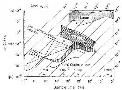 Figure 6: Comparison of time-transfer techniques to the classical GPS Common View mode [Lewandowski W. and Azoubib J., 2000][3].
References
- ^ a b c d e f [Lombardi M. et al., 2001] Lombardi M., Nelson L., Novick A. and Zhang V., 2001, ‘Time and Frequency Measurements Using The Global Positioning System’, The International Journal of Metrology, July
- ^ a b [Petit G. and Jiang Z., 2008] Petit G. and Jiang Z., 2008, ‘GPS All in View time transfer for TAI computation’, Metrologia, No. 45, page 35-45
- ^ [Lewandowski W. and Azoubib J., 2000] Lewandowski W. and Azoubib J., 2000, ‘Time Transfer and TAI’, Proceedings of the 2000 IEEE/EIA International, page 586-597
Credits
The information presented in this NAVIPEDIA’s article is an extract of the work performed by Fernando Martín Porqueras in the Technical University of Catalonia as part of the European Master of Research on Information and Communication Technologies
