If you wish to contribute or participate in the discussions about articles you are invited to contact the Editor
Multipath
| Fundamentals | |
|---|---|
| Title | Multipath |
| Author(s) | J. Sanz Subirana, J.M. Juan Zornoza and M. Hernández-Pajares, Technical University of Catalonia, Spain. |
| Level | Intermediate |
| Year of Publication | 2011 |
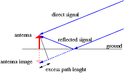
The interference by multipath is generated when a signal arrives, by different ways, at the antenna (see figure 1). Its principal cause is the antenna closeness to the reflecting structures, and it is important when the signal comes from the satellite with low elevation. This error is different for different frequencies. It affects the phase measurements, as well as the code measurements. In the case of the code, it can reach a theoretical value of 1.5 times the wavelength ("chip"). This means, for instance, that the multipath in the GPS C1 code can reach up to 450 meters (see table 1) although upper values more than 15 meters are difficult to observe. Typically, it is less than 2 or 3 meters.
In the case of the phase, its theoretical maximum value is a quarter of the wavelength. This means about 5 centimetres for the GPS L1 or L2 signals, but it is typically less than 1 centimetre.
The multipath error can be minimised improving the antenna quality, that is to say, making them to mitigate the signal coming from certain low elevation directions, and moving the antenna away from reflecting objects (when possible).
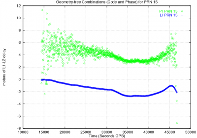
The effect of code multipath for low elevation rays is depicted in Figure 2, left, where the geometry-free combination of codes ([math]\displaystyle{ R_{_{P2}}-R_{_{P1}} }[/math]) and carrier ([math]\displaystyle{ \Phi_{_{L1}}-\Phi_{_{L2}} }[/math]) measurements are plotted for a satellite-receiver track. The largest noise in the edges is due to the low elevation rays at the rising and setting of the satellite. Notice that the carrier phase multipath (lower than [math]\displaystyle{ 1 }[/math] centimetre) can not be seen due to the scale of the figure, with [math]\displaystyle{ 2 }[/math] meter tics.
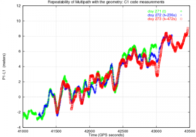
The geometrical nature of multipath is illustrated in Figure 2, right, where the code minus phase combination [math]\displaystyle{ R_{_{P1}}-\Phi_{_{L1}} }[/math] is plotted for a given satellite for three consecutive days. The measurements were collected with a static GPS receiver and, thence, the geometry of satellite-receiver rays repeat every sidereal day [footnotes 1]. Notice in this figure how the multipath signatures overlaps after aligning the plots to the first day (i.e., by shifting [math]\displaystyle{ 236 }[/math] and [math]\displaystyle{ 2 \times 236 }[/math] seconds, the second and third day plots, respectively) to account for the difference between the sidereal and the solar times. The global drift is due to the ionospheric refraction [math]\displaystyle{ 2 \alpha I }[/math], (see equation 1):
- [math]\displaystyle{ R_1- \Phi_1=2 \tilde{\alpha}_1 I +Bias+\mathcal{M}+\varepsilon \qquad \mbox{(1)} }[/math]
Figure 2: Satellite Effect of code multipath on GPS signals. Figure at left shows the "butterfly effect" due to the largest multipath at the satellite rising and setting (i.e., due to the low elevation rays). The figure at right shows the repeatability of multipath signatures with the geometry: The code minus phase signal combination [math]\displaystyle{ R_{_{P1}}-\Phi_{_{L1}} }[/math] is plotted for a given satellite for three consecutive sidereal days. The drift is due to the ionospheric refraction. Note: Data set collected on 28-30 September 1998, in Barcelona (Spain), with the single frequency Lassen-SK8, Trimble, receiver)
Notes
- ^ That is every 24 hours minus 236 seconds of GPS time.


