If you wish to contribute or participate in the discussions about articles you are invited to contact the Editor
Correlators
| Receivers | |
|---|---|
| Title | Correlators |
| Author(s) | GMV |
| Level | Advanced |
| Year of Publication | 2011 |
Correlations are the key operation for a GNSS receiver to synchronize with the incoming signal, generate GNSS observables and retrieve the navigation message that will be used to provide a navigation solution later on.
The reason is that GNSS signals transmit a ranging code modulated into the carrier, also called Pseudo-Random Noise (PRN) code, which not only spreads the spectrum but also allows retrieving ranging information.
Pseudo-Random Noise Codes
Pseudo Random Noise (PRN) Codes - also called ranging codes - are a sequence of pulses that are used by GNSS to spread the spectrum of the transmitted signal. Several types of codes are used to achieve this goal. As an example, GPS L1 C/A uses Gold codes[1] that are actually a combination of two maximum sequence codes [2]. GLONASS uses only one maximum length code: since it uses FDMA, low cross-correlation characteristics are not so critical for this system. Galileo on the other hand uses tiered codes, a combination of small medium length primary code with a smaller length code secondary code. Some of these secondary codes are memory codes, which are not generated through Linear feedback shift register (LFSR)[3] like the others. Instead, they are stored in the local memory. The advantage of these codes is that they are harder to decode by unauthorized users. Please refer to the respective SIS ICDs for further information on the codes used by each system.
The choice of these codes for each specific signal is a trade-off between:
- Code length: the longer the code, the smaller the code cross-correlation properties and the higher number of codes can be generated. Nevertheless, the receiver takes more time to acquire the signal. Furthermore, the code length is limited by the navigation symbol boundaries, hence related to bit rate
- Code chipping rate: the higher the chipping rate, the wider the signal bandwidth will be (imposing wider front ends at the receiver), but better ranging accuracies can be potentially achieved
- Code characteristics: although not so critical in FDMA GNSS (e.g. GLONASS) that guarantee satellite separation using different frequencies, ranging codes are selected to have high auto-correlation values and low cross-correlation values. This characteristic guarantees the separation between satellites that use concurrent spectrum (e.g. GPS and Galileo).
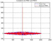
As an example, Figure 1 depicts the autocorrelation of GPS PRN1 and the cross correlation between GPS PRN1 and GPS PRN17.
It can be seen that no matter the delay considered, the cross-correlation always provides low values, while the auto-correlation (correlation between PRN1 and itself) only presents a peak when both replicas are aligned.
The peak can be seen at delay = 1023 since the length of the code is 1023 chips. In addition, when both replicas are aligned, the peak is the sum of all absolute values of the chips, yielding the code length: 1023.
This is observed since no noise was considered.
Correlation: Mathematical Model
The continuous correlation between two signals, x and y, in the time domain, can be defined as:
[math]\displaystyle{ R_{xy}(\tau) = \int_{-\infty}^\infty x(t)y^{*}(t-\tau) dt }[/math]
where "*" denotes the complex conjugate.
When x=y, this is also called Autocorrelation function.
Considering a low-pass signal with constant power, as the ones processed by GNSS receivers, the correlation function can be written as:
[math]\displaystyle{ R_{xy}(\tau) = \lim_{T \to \infty} \frac{1}{2T} \int_{-\infty}^\infty x(t)y^{*}(t-\tau) dt }[/math]
The power spectral density of a signal is defined by the Fourier transform of the autocorrelation function and can be written as:
[math]\displaystyle{ G(f) = \int_{-\infty}^\infty R_{xx}(\tau) exp[-j2\pi f \tau] dt }[/math]
Finally, since GNSS receivers deal with digitized signals, the discrete auto-correlation function is given by:
[math]\displaystyle{ R_{xx}(k) = \sum_{n=-\infty}^\infty x[n]x^{*}[n-k] }[/math]
Block Diagram
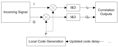
The block diagram zoomed-in from the Digital Signal Processing block is depicted in Figure 2, where the Doppler removal block is omitted for clarity reasons. Furthermore, only the generation of the Prompt (P) replica is considered, i.e. the replica that is generated at the receiver so as to align with the incoming code.
The local code is generated according to an input “code delay” which indicates the quantity by which the code should be shifted before correlating it with the incoming signal. From the previous definitions, it is clear that when the local replica is aligned with the incoming signal, the correlation output will be maximum.
Since real life signals are subject to noise and other disturbances, the assessment of the correlation output is solely performed on a single shot. In fact, the receiver uses Integration & Dump (I&D) blocks to integrate the correlation outputs over time. The main objective is to combine the correlations from consecutive PRN codes in order to increase the power of any potential peak and to reduce the inherent noise. GNSS receivers often use a combination between coherent and non-coherent integrations, as further discussed here.
Effect of the Modulation on Autocorrelation Function
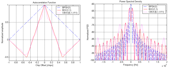
The shape of the auto-correlation function is affected not only by the PRN code characteristics but also by the signal modulation. As an example, Figure 3 presents the normalized auto-correlation functions for:
- BPSK(1): used in GPS L1 C/A
- BOC(1,1): used in Galileo E1-B
- CBOC(6,1,1/11): used in GPS L1-M and Galileo E1-B
Bearing in mind that GNSS receivers aim at tracking the peak of the auto-correlation function using the prompt correlator[footnotes 1]. and adjusting its delay to keep high auto-correlation values, it is rather intuitive to infer that narrower autocorrelation peaks potentially yield better accuracies. In fact, a badly formed prompt local replica will lead to a lower correlation output for small variations around the center. As a consequence, it can be inferred that BOC modulations can reach better accuracies, being CBOC the best one, when looking at the GPS and Galileo Open Service signals in the L1 band. When looking at the Power Spectral Density, this can be explained by the wider bandwidths of the BOC signals. The drawback is that the receiver needs wider front ends in order to process the full signal.
The main drivers for including the BOC modulations in GNSS are[4]:
- To guarantee compatibility while supporting interoperability among GNSS
- To provide signals that are more robust in harsh environments such as noise, multipath and interference
- To reduce self-interference
Furthermore, BOC modulations present additional side peaks (in Figure 3 for offsets of 0.5 chips). At receiver level, additional processing may be required in order to guarantee that the tracking loops are actually tracking the main peak and not one of the side peaks.
Finally, when the lag between the local replica and the incoming signal is higher than 1 chip, the auto-correlation is minimum and only noise will be observed.
Notes
Related articles
References
- ^ http://en.wikipedia.org/wiki/Gold_code
- ^ http://en.wikipedia.org/wiki/Maximum_length_code
- ^ http://en.wikipedia.org/wiki/LFSR
- ^ “Status of Galileo Frequency and Signal Design”, Guenter W. Hein, Jeremie Godet, Jean-Luc Issler, Jean-Christophe Martin, Philippe Erhard, Rafael Lucas-Rodriguez and Tony Pratt, Proceedings of the 15th International Technical Meeting of the Satellite Division of The Institute of Navigation (ION GPS 2002), September 24 - 27, 2002, Oregon Convention Center, Portland, OR


