If you wish to contribute or participate in the discussions about articles you are invited to contact the Editor
GNSS Interference Model: Difference between revisions
Carlos.Lopez (talk | contribs) No edit summary |
Carlos.Lopez (talk | contribs) No edit summary |
||
| Line 18: | Line 18: | ||
[[Category:Fundamentals]] | |||
[[Category:GNSS Signals]] | |||
Moreover, we define the equivalent noise power density of each of the interfering signals as: | Moreover, we define the equivalent noise power density of each of the interfering signals as: | ||
Revision as of 14:30, 3 November 2011
| Fundamentals | |
|---|---|
| Title | GNSS Interference Model |
| Author(s) | J.A Ávila Rodríguez, University FAF Munich, Germany. |
| Level | Advanced |
| Year of Publication | 2011 |
In this article we present the most important expressions that are necessary to assess the degradation that a signal causes on another signal in the shared band. As we have shown in MBOC Modulation, the methodology is based on the idea of measuring the degradation of a desired signal in terms of the reduction of its effective C/N0 (this figure is also analysed in Equivalent C/N0 in presence of Interference). This can be caused by either the background noise where all the non GNSS signals are included or by another interfering signal of the same or similar nature. To this group belong all the types of interference from other GNSS signals. We can further distinguish the different GNSS interference sources following this classification:
- [math]\displaystyle{ I_{Intra} }[/math]: This type of interference is commonly known as intra-system interference and is due to the signals coming from satellites that belong to the same system as the desired signal.
- [math]\displaystyle{ I_{Interop} }[/math]: This type of interference corresponds to the equivalent noise introduced in the receiver by an interfering signal coming from a satellite of a different constellation but with the same signal structure as that of the desired signal.
- [math]\displaystyle{ I_{Inter} }[/math]: This type of interference comes from signals with a different signal structure no matter whether the signal belong to the same system or a different one.
If we put now all the GNSS sources of interference together, we have as interfering power:
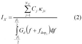
Moreover, we define the equivalent noise power density of each of the interfering signals as:
- where
- [math]\displaystyle{ X }[/math] defines the type of interference according to the definitions above,
- [math]\displaystyle{ N_X }[/math] represents the number of satellites,
- [math]\displaystyle{ C_j }[/math] is the received power of satellite j,
- [math]\displaystyle{ \Beta_r }[/math] is the receiver bandwidth,
- [math]\displaystyle{ G_d }[/math] is the power spectral density of the desired signal s,
- [math]\displaystyle{ f_{dop-s} }[/math] is the doppler frequency offset of the desired signal s,
- [math]\displaystyle{ K_{js} }[/math] is the spectral separation coefficient between signal j and the desired signal s. This is defined as follows:
- where,
- [math]\displaystyle{ G_j^i(f) }[/math] is the power spectral density of the interfering signal j
- [math]\displaystyle{ f_{dop_s} }[/math] is the doppler frequency offset of the desired signal j.
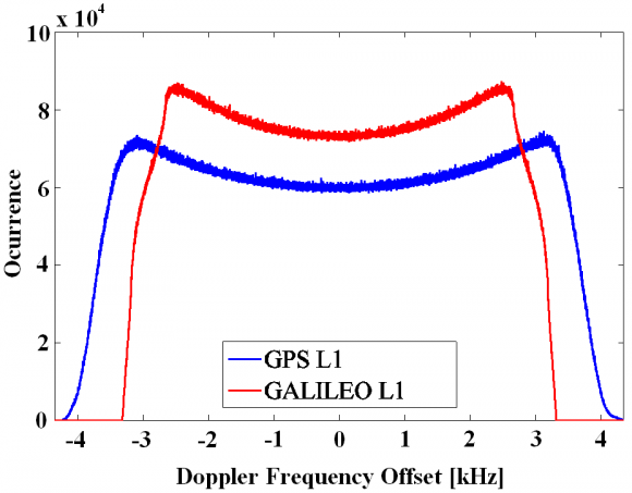
The GNSS receiver of our model is supposed to stay stationary at the earth’s surface so that only the motion of the satellites will be responsible for the Doppler offsets observed at user level. Moreover, we know that while for GPS the absolute Doppler frequency offset does not exceed 4.4 kHz, the range is narrower for Galileo, being the maximum value of 3.3 kHz in the E1/L1 band as shown in Figure 1 [S. Wallner et al., 2005] [1]:
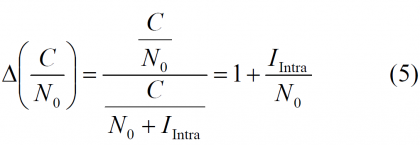
Once we have defined mathematically the shape of the different sources of interference, we can now compute the degradation suffered by a receiver due to other signals. As we said at the beginning, the interference of one system onto another one is given by the reduction of the effective [math]\displaystyle{ C/N_0 }[/math], which can be expressed as follows:
where N0 refers to the noise floor. Furthermore, we assume a noise value of -201.5 dBW/Hz for all the purposes. In addition, the degradation of the effective [math]\displaystyle{ C/N_0 }[/math] due to intra-system interference can be thus expressed as follows:
Equally, for the case of the degradation caused by the inter-system interference we have the following expression:
Now that we have the necessary mathematical expressions to calculate the degradation suffered by a receiver according to this simplified model, we only need to obtain the power of the desired and interfering signals at each point of the earth. To do that, we have to simulate the satellite positions and movements and account for the attenuations of the signal from the satellite to the receiver. Indeed, once we know the minimum received powers as given in [Galileo SIS ICD, 2008] [2], [GPS ICD 200][3], [GPS ICD-705, 2005] [4] and [GPS ICD-800, 2006] [5] we obtain the transmission power Pj of each satellite as done by [S. Wallner et al., 2005] [1] and we can derive the power received at user level at every point of the earth according to:
- where
- [math]\displaystyle{ P_j }[/math] depicts the transmission power from satellite j,
- [math]\displaystyle{ G_j }[/math] is the satellite antenna gain,
- [math]\displaystyle{ A_dist }[/math] is the attenuation due to the distance between the satellite and the user,
- [math]\displaystyle{ A_pol }[/math] is the attenuation of the signal due to the mismatch losses in the polarization,
- [math]\displaystyle{ A_atm }[/math] is the attenuation of the signal due to the atmosphere, and
- [math]\displaystyle{ G_user }[/math] is the receiver antenna gain.
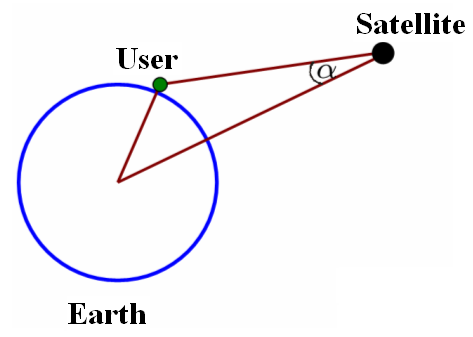
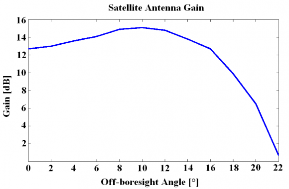
The satellite antenna gain [math]\displaystyle{ G_i }[/math] Gj is a function of the Off-Boresight Angle [math]\displaystyle{ \alpha }[/math] as defined next:
being the typical satellite antenna gain as shown in the following figure:
Additionally, the signal attenuation due to the free-space losses [math]\displaystyle{ A_dist }[/math] is given by:
- where,
- [math]\displaystyle{ c }[/math] c is the speed of light
- [math]\displaystyle{ d }[/math] d is the distance between the satellite and the user
- and [math]\displaystyle{ f_c }[/math] is the carrier frequency
References
- ^ a b [S. Wallner et al., 2005] S. Wallner, G.W. Hein, J.-A. Avila Rodriguez, T. Pany, A. Posfay, Interference Computations Between GPS and Galileo, Proceedings of the International Technical Meeting of the Institute of Navigation, ION-GNSS 2005, 13-16 September, 2005, Long Beach, California, USA.
- ^ [Galileo SIS ICD, 2008] Galileo Open Service Signal In Space Interface Control Document (OS SIS ICD) Draft 1 01/02/2008, 2008, European Space Agency / Galileo Joint Undertaking http://www.galileoju.com
- ^ [GPS ICD 200, 2006] IS-GPS-200 Revision D, IRN-200D-001:NAVSTAR GLOBAL POSITIONING SYSTEM Navstar GPS Space Segment/Navigation User Interface, dated 7 March 2006.
- ^ [GPS ICD-705, 2005] IS-GPS-705, IRN-705-003: Navstar GPS Space Segment/User Segment L5 Interfaces, 22 September 2005.
- ^ [GPS ICD-800, 2006] Draft IS-GPS-800 Navstar GPS Space Segment/User Segment L1C Interfaces, 19 April 2006.

