If you wish to contribute or participate in the discussions about articles you are invited to contact the Editor
QZSS Signal Plan: Difference between revisions
Carlos.Lopez (talk | contribs) No edit summary |
Carlos.Lopez (talk | contribs) No edit summary |
||
| Line 27: | Line 27: | ||
[[Category:Fundamentals]] | [[Category:Fundamentals]] | ||
[[Category:GNSS Signals]] | [[Category:GNSS Signals]] | ||
[[Category: | [[Category:QZSS]] | ||
Revision as of 15:25, 19 September 2011
| Fundamentals | |
|---|---|
| Title | QZSS Signal Plan |
| Author(s) | J.A Ávila Rodríguez, University FAF Munich, Germany. |
| Level | Advanced |
| Year of Publication | 2011 |
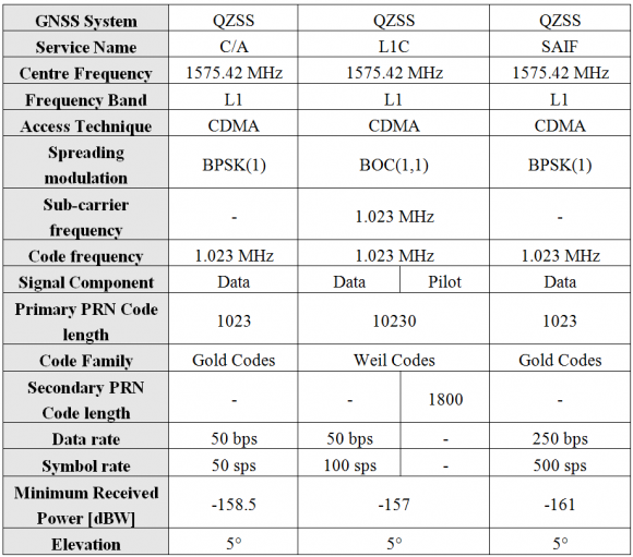
QZSS and GPS have the highest level of interoperability among all the Satellite Navigation Systems as we will see in the following tables. In fact, the spectral properties are equivalent to those of GPS. The characteristics of the different signals in particular are summarized in detail in the following tables. For the case of the L1 band the technical characteristics of the QZSS signals are presented next:
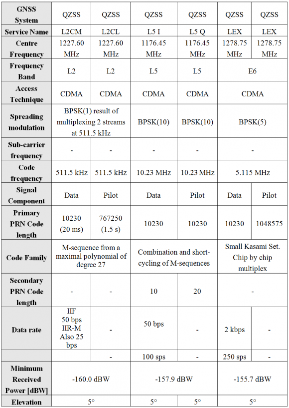
Equally, for L2, L5 and E6, the technical characteristics of the QZSS signals are summarized in the following table. As we can clearly recognize, except for the LEX signal in E6, QZSS and GPS are practically identical. It is interesting to note that this signal makes use of a very interesting multiplexing scheme for its experimental LEX signal, based on Code Shift Keying (CSK) [QZSS SIS ICD][1].
As a summary, the signal plan of QZSS is shown in the next figure:
References
- ^ [QZSS SIS ICD, 2007] Quasi Zenith Satellite System Navigation Service, Interface Specification for QZSS (IS-QZSS), Japan Aerospace Exploration Agency, January 22, 2007.


