If you wish to contribute or participate in the discussions about articles you are invited to contact the Editor
GPS Navigation Message: Difference between revisions
m (→References) |
mNo edit summary |
||
| Line 6: | Line 6: | ||
|YearOfPublication=2011 | |YearOfPublication=2011 | ||
}} | }} | ||
==Introduction== | |||
The original GPS satellites transmit signals centred on two radio frequencies in the L band, referred to as Link 1 (L1) and Link 2 (L2)<ref group="footnotes">They also transmit two additional signals at frequencies referred as L3 (associated to the Nuclear Detonations Detection System) and L4 (for other military purposes).</ref>. They are right-hand circularly polarised and their frequencies are derived from a fundamental frequency <math>f_0 = 10.23 MHz</math>, generated by on board atomic clocks. | The original GPS satellites transmit signals centred on two radio frequencies in the L band, referred to as Link 1 (L1) and Link 2 (L2)<ref group="footnotes">They also transmit two additional signals at frequencies referred as L3 (associated to the Nuclear Detonations Detection System) and L4 (for other military purposes).</ref>. They are right-hand circularly polarised and their frequencies are derived from a fundamental frequency <math>f_0 = 10.23 MHz</math>, generated by on board atomic clocks. | ||
<math> | <math> | ||
Revision as of 17:54, 20 January 2011
| Fundamentals | |
|---|---|
| Title | GPS Navigation Message |
| Author(s) | J. Sanz Subirana, JM. Juan Zornoza and M. Hernandez-Pajares, University of Catalunia, Spain. |
| Level | Basic |
| Year of Publication | 2011 |
Introduction
The original GPS satellites transmit signals centred on two radio frequencies in the L band, referred to as Link 1 (L1) and Link 2 (L2)[footnotes 1]. They are right-hand circularly polarised and their frequencies are derived from a fundamental frequency [math]\displaystyle{ f_0 = 10.23 MHz }[/math], generated by on board atomic clocks.
[math]\displaystyle{
\begin{array}{lcl}
L1 = 154 \times 10.23 MHz = 1575.420 MHz \\
L2 = 120 \times 10.23 MHz = 1227.600 MHz
\end{array}
 }[/math]
Two services are available from GPS system:
- SPS: The Standard Positioning Service is an open service, free of charge for worldwide users. This is a single frequency service in the frequency band L1.
- PPS: The Precise Positioning Service is restricted by cryptographic techniques to military and authorised users. Two navigation signals are provided in two different frequency[footnotes 2] bands L1 and L2.
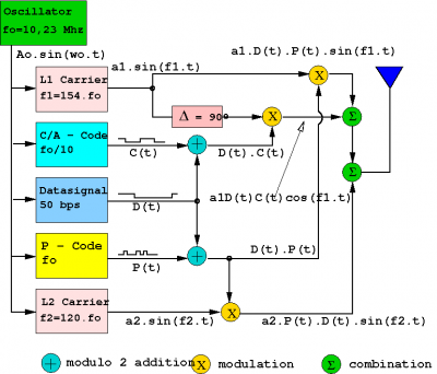
The GPS uses the Code Division Multiple Access (CDMA) technique to send different signals on the same radio-frequency, and the modulation method used is the Binary Shift Phase Keying (BPSK). The following types of PRN codes and messages are modulated over the two carriers (see figure 1):
- Coarse/Acquisition code [C/A(t)]: it is also known as civilian code. This sequence contains 1023 bits and is repeated every millisecond (i.e, achipping-rate of 1.023 M bps). Thence, the duration of each C/A-code chip is 1μs, which means a chip-width or wavelength of 293.1m. This code is modulated only on L1. The C/A-code defines the Standard Positioning Service (SPS).
- Precision code [P(t)]: it is reserved for military use and authorised civilian users. The sequence is repeated every 266 days (38 weeks) and a weekly portion of this code is assigned to every satellite, called PRN sequence. Its chipping-rate is 10 M bps, which leads to a wavelength of 29.31 m. It is modulated over both carriers L1 and L2. The P-code defines the Precise Positioning Service (PPS).
- Navigation message [D(t)]: it is modulated over both carriers at 50 bps, re- porting information about ephemeris and satellite clock drifts, ionospheric model coefficients, constellation status, etc.
[math]\displaystyle{
\begin{array}{lcl}
L1(t) = a_1P (t)D(t) sin(f_1t + \phi P_1 ) + a_1C/A(t)D(t) cos(f_1t + \phi c) \\
L2(t) = a_2P (t)D(t) sin(f_2t + \phi P_2 )
\end{array}
 }[/math]
In order to restrict civilian users access to full system accuracy, the following protections were introduced:
- S/A or Selective Availability: intentional satellite clock degradation (process-δ) and ephemeris manipulation (process-ε). The effect on horizontal positioning implies going from about 10 m (S/A=off) to 100 m (S/A=on) (2σ-error). The process δ acts directly over satellite clock fundamental frequency, which has a direct impact on pseudoranges to be calculated by user’s receivers. The process ε consists in truncating information related to the orbits. USA President Bill Clinton ordered the cessation of GPS Selective Availability on May 1st, 2000.
- A/S or Anti-Spoofing: it consists in P code encryption by combining it with a secret W code, resulting in the Y code, which is modulated over the two carriers L1 and L2. The purpose is to protect military receivers from an adversary transmitting a fault copy of GPS signal to mislead the receiver, and to deny the access of non authorised users to the precise ranging code P in L1 and L2 frequencies, being solely C/A code available over L1.
The signal structure is summarised in the following figure 1 and table 1:
GPS signal modernisation
The GPS signal modernisation will introduce the additional Link 5 (L5) frequency and several new ranging codes on the different carrier frequencies. They are referred to as the civil signals L2C, L5C and L1C and the military code M. All of them are right-hand circularly polarised.
The modernisation of the GPS system began in 2005 with the launch of the first IIR-M satellite. This satellite supported the new military M-signal and the second civil signal L2C. This new L2C civil signal is specifically designed to meet commercial needs, allowing the development of low-cost dual frequency civil GPS receivers. It has a lower tracking threshold and better correlation properties than the L1-C/A signal due to the longer codes, which leads to faster signal acquisition, enhanced reliability, and greater operating range.
The L2C code is composed of two ranging codes multiplexed in time: The L2 Civil Moderate (L2CM) code and the L2 Civil Long (L2CL) code. L2C is broadcast at a higher effective power level than the original L1-C/A signal. This fact, together with its powerful cross-correlation properties, facilitates tracking with large signal level variations from satellite-to-satellite[footnotes 3], making it easier the reception under trees and even indoors. This signal will also be interoperable with the Quasi-Zenith Satellite System (QZSS) under development by Japan. At April 2009 there were seven GPS satellites broadcasting L2C (PRN01, 07, 12, 15, 17, 29, 31)[footnotes 4].
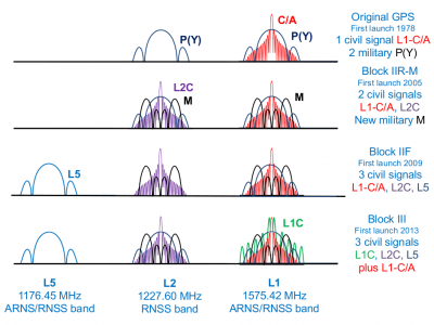
The military M-code signals are designed to use the edges of the band with only minor signal overlap with the preexisting C/A and P(Y) signals (see figure 2). This military M-code is modulated into L1 and L2 carriers using the Binary Offset carrier (BOC) scheme. It has been designed for autonomous acquisition, so that a receiver will be able to acquire the M code signal without access to C/A code or P(Y) code signals.
The modernisation continues with the launch of the Block IIF satellites (the first one was launched on May 28th 2010) that include, for the first time, the third civil signal on L5 band (i.e., within the highly protected Aeronautical Radio Navigation Service (ARNS) band). This new L5C signal has a new modulation type and it was designed to meet Safety of Life (SoL) requirements, mainly for civil aviation. There are two signal components: The In-phase component (I5 or L5-I) with data and ranging code, both modulated via BPSK onto the carrier, and the Quadrature component (Q5 or L5-Q), with no data, but also having a ranging code BPSK modulated onto the carrier. This signal has an improved code/carrier tracking loop and its high power and signal design provide robustness against interference. Moreover, its higher chipping rate than the C/A-code (see table 2) provides superior multipath performance.
The next step will go on with the Block-III satellites, which will provide the fourth civil signal on L1 band (L1C). This signal is designed to enable interoperability between GPS and international satellite navigation systems (such as Galileo[footnotes 5]). The Multiplexed Binary Offset Carrier (MBOC) modulation is used to improve mobile reception in cities and other challenging environments. L1C is composed by L1CD data channel and L1CP pilot channel. This signal will broadcast at the same frequency as the original L1-C/A signal, which will be retained for backwards compatibility.
Figure 2 shows a layout of the different GPS signals and ranging codes for the different modernisation phases.
Table 2 shows a summary of the current and future GPS signals, frequencies and applied modulations. The ranging Code Rate and Data Rate are also given in the table.
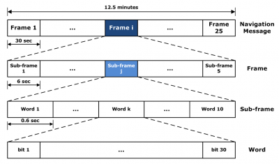
Every satellite receives from the ground antennas the navigation data which is sent back to the users through the navigation message. The Navigation Message provides all the necessary information to allow the user to perform the positioning service. It includes the Ephemeris parameters, needed to compute the satellite coordinates with enough accuracy, the Time parameters and Clock Corrections, to compute satellite clock offsets and time conversions, the Service Parameters with satellite health information (used to identify the navigation data set), Ionospheric parameters model needed for single frequency receivers, and the Almanacs, allowing the computation of the position of ”all satellites in the constellation”, with a reduced accuracy (1 − 2 km of 1-sigma error), which is needed for the acquisition of the signal by the receiver. The ephemeris and clocks parameters are usually updated every two hours, while the almanac is updated at least every six days. The current “legacy” Navigation Message (NAV) is modulated on both carriers at 50 bps. The whole message contains 25 pages (or ’frames’) of 30 seconds each, forming the master frame that takes 12,5 minutes to be transmitted. Every frame is subdivided into 5 sub-frames of 6 seconds each; in turn, every sub-frame consists of 10 words, with 30 bits per word (see figure 3). Every sub-frame always starts with the telemetry word (TLM), which is necessary for synchronism. Next, the transference word (HOW) appears. This word provides time information (seconds of the GPS week), allowing the receiver to acquire the week-long P(Y)-code segment.
The content of every sub-frame is as follows:
- Sub-frame 1: contains information about the parameters to be applied to satellite clock status for its correction. These values are polynomial coefficients that allow converting time on board to GPS time. It also has information about satellite health condition.
- Sub-frames 2 and 3: these sub-frames contain satellite ephemeris.
- Sub-frame 4: provides ionospheric model parameters (in order to adjust for ionospheric refraction), UTC information (Universal Coordinate Time), part of the almanac, and indications whether the Anti-Spoofing, A/S, is activated or not (which transforms P code into the encrypted Y code).
- Sub-frame 5: contains data from the almanac and the constellation status. It allows to quickly identify the satellite from which the signal comes. A total of 25 frames are needed to complete the almanac.
Sub-frames 1, 2 and 3 are transmitted with each frame (i.e., they are repeated every 30 seconds). Sub-frames 4 and 5 contain different pages (25 pages each) of the navigation message (see figure 3). Thence, the transmission of the full navigation message takes 25 × 30 seconds = 12.5 minutes. The content of sub-frames 4 and 5 is common for all satellites. Thence, the almanac data for all in orbit satellites can be obtained from a single tracked satellite. GPS modernisation introduces four new data messages: CNAV, CNAV-2, MNAV and L5-CNAV. The first three are civil messages, while the MNAV is a military message. They provide more accurate and frequent message data than the legacy navigation message (NAV).
CNAV and MNAV have a similar structure and modernised data format. The new format allows more flexibility, better control and improved content. Its design replaces the use of frames and sub-frames of data (repeating in a fixed pattern) of the original “legacy” NAV by a packetised message-based communications protocol, where individual messages can be broadcast in a flexible order with variable repeat cycles. Moreover, Forward Error Correction (FEC) and advanced error detection (such as a CRC) are used to achieve better error rates and reduced data collection times. Furthermore, the MNAV includes new improvements for the security and robustness of this military message. A preliminary description of the CNAV structure can be found in the Interface Specification (IS)-GPS-200D [GPS Joint Program Office, 2004]. It includes up to 63 different message types, of which 15 types have already been defined. The L5-CNAV is modulated onto L5I signal component, containing basically the same information data as NAV and CNAV, but in a different format. The CNAV-2 provides more accurate data, it is modulated onto L1CD, and it is divided into frames, which are sub-divided into three subframes.
User domain GPS performance
The positioning and timing accuracy for the GPS Standard Positioning Service (SPS) is shown in table 3. These figures are taken from the performance specifications of the SPS [DoD, USA, 1995] and [DoD, USA, 2008] documents, and are based on a 95th percentile level and Signal In Space (SIS) only. The specifications for the Precise Positioning Service (PPS) are quite similar to those of SPS with Selective Availability unable (S/A=off), see [DoD, USA, 2007]. These values are very conservative, being the actual performances usually better than these official values. Indeed, SPS horizontal and vertical accuracies are better than 7 and 12 meters, respectively, the 95 percent of time that are currently observed. The modernised GPS, with the new L5 signal, is expected to provide civil users with horizontal accuracies of about 2−3 meters 95 percent of time, “as good as PPS users currently enjoy” [Mc Donald and Hegarty, 2000].
Notes
- ^ They also transmit two additional signals at frequencies referred as L3 (associated to the Nuclear Detonations Detection System) and L4 (for other military purposes).
- ^ Transmission in two frequencies allows dual-frequency user receivers to cancel out the ionospheric refraction, which is one of the main sources of error (See: Atmospheric Effects Modelling).
- ^ C/A code acquisition may be impossible for very weak signals in the presence of a strong C/A signal.
- ^ Satellite PRN01/SVN49 (launched on March 2009), also began transmitting the data-less L5 signal. See the GPS Constellation status
- ^ Originally, this signal was developed as a common civil signal for GPS and Galileo, but new satellite navigation providers are adopting L1C as a future standard for international interoperability. QZSS (Japan), BEIDOU/COMPASS (China) and IRNSS (India) all plan to broadcast L1C.
References
- DoD, USA, 1995 Global Positioning System Standard Positioning Service Performance Standard.
- DoD, USA, 2007 Global Positioning System Precise Positioning Service Performance Standard.
- DoD, USA, 2008 Global Positioning System Standard Positioning Service Performance Standard.
- GPS Joint Program Office, 2004 Navstar GPS Space Segment / Navigation User Interfaces (IS-GPS-200D).
- Mc Donald, K. and Hegarty, C., 2000. Modernization GPS Performance Capabilities. In: Proceedings of ION 56th Annual Meeting, 25-26 June 2000, San Diego California USA, pp. 242-249.


