If you wish to contribute or participate in the discussions about articles you are invited to contact the Editor
Intervoting (Interplex plus Majority Voting): Difference between revisions
Carlos.Lopez (talk | contribs) (Created page with "{{Article Infobox2 |Category=Fundamentals |Title={{PAGENAME}} |Authors= J.A Ávila Rodríguez, University FAF Munich, Germany. |Level=Advanced |YearOfPublication=2011 }} == Intr...") |
Carlos.Lopez (talk | contribs) No edit summary |
||
| Line 1: | Line 1: | ||
{{Article Infobox2 | {{Article Infobox2 | ||
|Category=Fundamentals | |Category=Fundamentals | ||
|Authors=J.A Ávila Rodríguez, University FAF Munich, Germany. | |||
|Authors= J.A Ávila Rodríguez, University FAF Munich, Germany. | |||
|Level=Advanced | |Level=Advanced | ||
|YearOfPublication=2011 | |YearOfPublication=2011 | ||
|Title={{PAGENAME}} | |||
}} | }} | ||
== Introduction == | == Introduction == | ||
| Line 202: | Line 201: | ||
==References== | ==References== | ||
<references/> | <references/> | ||
== Credits == | |||
The information presented in this NAVIPEDIA’s article is an extract of the PhD work performed by Dr. Jose Ángel Ávila Rodríguez in the FAF University of Munich as part of his Doctoral Thesis “On Generalized Signal Waveforms for Satellite Navigation” presented in June 2008, Munich (Germany) | |||
[[Category:Fundamentals]] | [[Category:Fundamentals]] | ||
[[Category:GNSS Signals]] | [[Category:GNSS Signals]] | ||
Latest revision as of 09:12, 25 November 2011
| Fundamentals | |
|---|---|
| Title | Intervoting (Interplex plus Majority Voting) |
| Author(s) | J.A Ávila Rodríguez, University FAF Munich, Germany. |
| Level | Advanced |
| Year of Publication | 2011 |
Introduction
Majority voting presents interesting characteristics with respect to current known multiplexing techniques, being majority voting an extremely efficient technique when the number of signals to multiplex increases. On the other hand, it can be shown that while the number of signals to multiplex is not higher than three, interplex is optimum in the sense of presenting minimum multiplex losses, especially when the power distribution of the different signals varies considerably. For more than three signals, however, majority voting is shown to outperform interplex.
When both multiplex techniques are compared, one comes to the natural question of whether it would not be possible to have the best of both techniques in one single multiplexing. The answer to this is that it is in fact possible. Such a modulation receives the name of Intervoting (Interplex + Majority Voting).
Origins of Intervoting
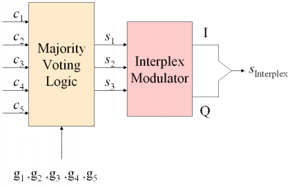
[G. L. Cangiani et al., 2002][1] have proved that the interplex modulation can be further exploited and generalized to the intervote multiplex, where elementary majority voting techniques are combined with the interplex modulation. Next figure shows schematically how the intervoting modulation works.
As we can recognize, an intervote modulator includes a majority voting logic unit and an interplex modulator. The majority voting logic receives as input a number of signal codes with the commanded power ratios and delivers as output three signals that result from majority voting the inputs. In a particular implementation, two of the original input signals remain unchanged and are directly output, being the third output signal the majority vote of the rest of input signals. The majority vote signal and the other two uncombined signals are then fed into the interplex modulator as signals [math]\displaystyle{ s_1 }[/math],[math]\displaystyle{ s_2 }[/math] and [math]\displaystyle{ s_3 }[/math] to form the in-phase and quadrature components of the final composite signal.
Theory on Intervoting
The intervoting multiplex takes advantage of the positive aspects of both interplex and Majority voting while it gives a solution to the disadvantages that both present separately. In fact, while majority voting degrades its performance when the power difference between the different signals is considerable (this is the so-called small signal suppression problem), interplex reduces its efficiency as the number of signals increases. The combination of both techniques, is capable of elegantly coping with the drawbacks of the two multiplexing schemes, providing an efficient modulation for any number of signals and any arbitrary power distribution.
The particular intervoting multiplex that we analyze in this chapter combines five different signals, being three of them previously multiplexed using Majority Voting. It is important to mention that intervote could in principle be constructed with an interplex scheme that could accommodate more than three signals. Moreover, the total number of signals to multiplex could be in principle also higher. Without loss of generality, we will concentrate however in the following on this particular case given its simplicity and optimum combination of performance and flexibility.
As we can recognize from Figure 1, three of the signals are aggregated using majority voting and the resulting majority voted signal is then further multiplexed with the other two uncombined codes using interplex. This solution is especially optimum if the commanded power distribution could change during operation or would adopt any arbitrary set of values not necessarily fixed at the beginning. It is important to note that for a particular power distribution, a particular five signal interplex solution could possibly outperform intervote. Nevertheless, intervote will result in general in an improved efficiency for the majority of power distributions, bringing an additional flexibility in the design.
Let us assume five binary signals [math]\displaystyle{ \left \{ c_1,c_2,c_3,c_4,c_5 \right \} }[/math] with target commanded power distribution [math]\displaystyle{ \left \{ g_1,g_2,g_3,g_4,g_5 \right \} }[/math], being the gains defined in non-decreasing order such that [math]\displaystyle{ g_{n=1} \ge g_n }[/math]. As graphically depicted in Figure 1, each time there is a change in the target gains of the different signals, the majority voting logic of the intervote multiplexer has to determine which of the five signals is to be mapped [G. L. Cangiani et al., 2002][1] to which of the three interplex modulator inputs [math]\displaystyle{ s_1 }[/math], [math]\displaystyle{ s_2 }[/math] or [math]\displaystyle{ s_3 }[/math] during the period in which the particular targeted gains apply. Furthermore, the intervote logic has to decide which three codes are majority voted and where the two remaining codes input the interplex multiplexer such as to obtain the maximum global efficiency.
Since intervote bases on interplex to combine all the signals, we recall the general expression of the interplex multiplexing for the I and Q channels:
Where [math]\displaystyle{ s_1\left(t\right) }[/math], [math]\displaystyle{ s_2\left(t\right) }[/math] and [math]\displaystyle{ s_3\left(t\right) }[/math] are the input interplex components and the powers are all expressed in terms of [math]\displaystyle{ P_3 }[/math] with [math]\displaystyle{ P_3 = 1 }[/math]. Furthermore, the efficiency of the interplex modulation was shown to be:
As we mentioned above, all the permutations of five codes and all locations of the majority vote have to be tested to find the best global efficiency. Indeed, analysis shows that although a particular three-code combination could result in an optimum GMV solution for three particular codes, it is not always true that placing these three codes as input of the interplex and the other two uncombined in the other two interplex inputs would result in the best global intervote efficiency. This means in other words, that all possible combinations have to be tried to select the optimum configuration.
Fortunately, the number of efficiency evaluations significantly reduces if symmetry considerations are taken into account. In fact, a careful look at (1) reveals that only three logical possibilities for the majority vote placement are to be considered, namely [math]\displaystyle{ s_1 }[/math],[math]\displaystyle{ s_2 }[/math] or [math]\displaystyle{ s_3 }[/math]. In this manner, the number of combinations to try is of only [math]\displaystyle{ 3\binom{5}{3} = 30 }[/math]. Moreover, positions [math]\displaystyle{ s_2 }[/math] and [math]\displaystyle{ s_3 }[/math] are interchangeable so that the order does not affect the efficiency formulas as we will also prove next. According to this, only two placement options are possible for the majority vote signal:
- Majority Vote on I: As we have mentioned, placing the majority vote signal on either [math]\displaystyle{ s_2 }[/math] or [math]\displaystyle{ s_3 }[/math] is arbitrary in terms of the total efficiency. Therefore, the default majority vote signal will be taken to be [math]\displaystyle{ s_2 }[/math] in the following pages.
- Majority Vote on Q: In this case, the majority vote signal will be [math]\displaystyle{ s_1 }[/math].
Intervoting with Majority Vote on I
In the case that the majority voted signal is placed on I, the generic transmitted binary signals [math]\displaystyle{ \left \{ c_1,c_2,c_3,c_4,c_5 \right \} }[/math] can be assigned as follows [G. L. Cangiani et al., 2002][1]:
where the majority vote was arbitrarily placed on [math]\displaystyle{ s_2 }[/math] as we discussed above. Furthermore, the notation [math]\displaystyle{ s_2 = \left \{Maj \left(c_1,c_2,c_3\right),c_2,c_3\right\} }[/math] indicates that [math]\displaystyle{ s_2 }[/math] is an interlace of the majority vote of [math]\displaystyle{ c_1 }[/math],[math]\displaystyle{ c_2 }[/math]and [math]\displaystyle{ c_3 }[/math] with solo chips of [math]\displaystyle{ c_2 }[/math]and [math]\displaystyle{ c_3 }[/math], as described in Generalized Majority Voting (GMV): Sub-Majority Voting.
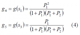
We further assume that the code set [math]\displaystyle{ \left \{ c_1,c_2,c_3,c_4,c_5 \right \} }[/math] has as target commanded power distribution [math]\displaystyle{ \left \{ g_1,g_2,g_3,g_4,g_5 \right \} }[/math]. According to this, the normalized interplex gain of [math]\displaystyle{ s_1 }[/math] and [math]\displaystyle{ s_3 }[/math] should be then [math]\displaystyle{ g_4 }[/math] and [math]\displaystyle{ g_5 }[/math] respectively. Taking now (1) into consideration this implies:
so that
Recalling the efficiency expression of the general interplex modulation (6)
the total efficiency of Intervoting with majority vote on I will be then as follows:
It is important to note that this expression is slightly different to the one corresponding for the general interplex case (8)
Indeed, the power allocated on the signal [math]\displaystyle{ s_2 }[/math] in the numerator has been corrected by the efficiency of the majority vote multiplex as not all the power allocated on [math]\displaystyle{ s_2 }[/math] corresponds in reality to the useful binary signals [math]\displaystyle{ c_1 }[/math],[math]\displaystyle{ c_2 }[/math] and [math]\displaystyle{ c_3 }[/math]. In fact, as shown in (9), part of the power goes lost in the majority voting reducing the efficiency from 1 to [math]\displaystyle{ \eta_{GMV} }[/math]. For the denominator, however, the whole power allocated on [math]\displaystyle{ s_2 }[/math] has to be considered including also the non-desired multiplex losses.
As we have mentioned above, signal [math]\displaystyle{ s_2 }[/math] is the majority vote of [math]\displaystyle{ c_1 }[/math],[math]\displaystyle{ c_2 }[/math] and [math]\displaystyle{ c_3 }[/math]. According to this, for the targeted power gains [math]\displaystyle{ g_1 }[/math],[math]\displaystyle{ g_2 }[/math] and [math]\displaystyle{ g_3 }[/math], the power gain of [math]\displaystyle{ s_2 }[/math]should be
or equivalently,
This can be further simplified if we recall that
Consequently,
or in a similar form
Using now equations (7), (5), (15) and (11) together, the total intervote efficiency when the majority vote is placed on I will be:
which can be further simplified and perfectly coincides with the expression shown by [G. L. Cangiani et al., 2002][1]:
It is interesting to note from the expression above that the position of [math]\displaystyle{ s_2 }[/math] and [math]\displaystyle{ s_3 }[/math] is insignificant what reinforces the comments we made in the section “Theory on Intervoting” as we anticipated that positions [math]\displaystyle{ s_2 }[/math] and [math]\displaystyle{ s_3 }[/math] are arbitrarily interchangeable. This is also valid for the case of Intervoting with Majority Vote on Q as we show next.
Intervoting with Majority Vote on Q
In the previous lines we have derived the analytical expression for the intervote efficiency when the majority vote signal is placed on I. In this chapter, we will repeat the same exercise for the case that the majority signal is placed on Q.
In this case, the transmitted signals can be assigned as follows [G. L. Cangiani et al., 2002][1]:
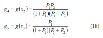
Since the code set [math]\displaystyle{ \left \{ c_1,c_2,c_3,c_4,c_5 \right \} }[/math] has as target commanded power distribution [math]\displaystyle{ \left \{ g_1,g_2,g_3,g_4,g_5 \right \} }[/math], the normalized interplex gain of [math]\displaystyle{ s_2 }[/math]and [math]\displaystyle{ s_3 }[/math] should be then [math]\displaystyle{ g_4 }[/math] and [math]\displaystyle{ g_5 }[/math] respectively. Taking (1) into consideration, this implies:
so that
Recalling now the expression for the efficiency of the intervote multiplex on I, the total efficiency with majority vote on Q adopts a slightly different form:
As we can recognize, the power allocated on signal [math]\displaystyle{ s_1 }[/math] in the numerator has been corrected by the efficiency of the majority vote multiplex following the same logic as in the case of majority vote on I. On the other hand, the whole power allocated on [math]\displaystyle{ s_1 }[/math] is considered for the denominator including also the non-desired multiplex losses as explained in previous chapter.
Signal [math]\displaystyle{ s_1 }[/math] is the majority vote of [math]\displaystyle{ c_1 }[/math],[math]\displaystyle{ c_2 }[/math] and [math]\displaystyle{ c_3 }[/math]. According to this, for the targeted power gains [math]\displaystyle{ g_1 }[/math],[math]\displaystyle{ g_2 }[/math] and [math]\displaystyle{ g_3 }[/math], the power gain of [math]\displaystyle{ s_1 }[/math]will be:
or
This can be further simplified as follows:
or equivalently
Putting now (20), (19), (11) and (14) together, the total intervote efficiency when the majority vote is placed on Q will be then:
which can be simplified coinciding with the expression of [G. L. Cangiani et al., 2002][1]:
In the previous lines we have derived the efficiency of the intervote multiplex for the case that the majority vote signal is either on I or on Q for a particular code set [math]\displaystyle{ \left \{ c_1,c_2,c_3,c_4,c_5 \right \} }[/math] with target commanded power distribution[math]\displaystyle{ \left \{ g_1,g_2,g_3,g_4,g_5 \right \} }[/math]. However, as we mentioned, to find the optimum code allocation it would be necessary to evaluate (7) and (20) for all the possible permutations.
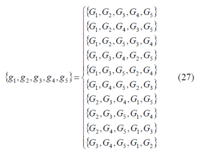
Fortunately, since the gains of the different codes are defined in non-decreasing order and the signal with the lowest power [math]\displaystyle{ c_1 }[/math]will never have solo chips in the majority vote signal, the number of permutations to assess reduces to ten for the case that we multiplex five signals. The ten standard permutations, as defined by [G. L. Cangiani et al., 2002][1] are presented next:
where [math]\displaystyle{ \left \{ g_1,g_2,g_3,g_4,g_5 \right \}=\left \{ G_1,G_2,G_3,G_4,G_5 \right \} }[/math] is the particular case that we covered in the previous two chapters. As underlined by [G. L. Cangiani et al., 2002][1], the indexes are increasing in positions 1, 2 and 3 of (27) in order to assure that the majority vote will never transmit the signal with the lowest power as solo chip. However, the situation for positions 4 and 5 is definitely different since here the order is significant. Indeed, depending on which signal occupies positions 4 and 5, this signal could be on I and Q resulting thus in different efficiency values as we have shown. According to this, twenty permutations are to be evaluated: the ten given by (27) plus another ten with positions four and five interchanged.
Once the previous equations determine with code set results in the optimum total efficiency, we would only have to form the majority vote of the three selected signals according to the theory presented in Generalized Majority Voting (GMV). In a next step, the resulting majority vote signal would be further interplex-multiplexed with the other two uncombined signals.
Last but not the least, it is important to mention that in principle any interplex solution could be employed in the intervote scheme to multiplex all the signals as defended and emphasized by [G. L. Cangiani et al., 2002][1]. In the particular but illustrating case of previous pages five signals were intervote-multiplexed using a three-input interplex. Nevertheless, as one can imagine, when the signals to multiplex increase, other interplex solutions could also be used. However, three seems to be a good compromise as then interplex behaves optimally.
References
Credits
The information presented in this NAVIPEDIA’s article is an extract of the PhD work performed by Dr. Jose Ángel Ávila Rodríguez in the FAF University of Munich as part of his Doctoral Thesis “On Generalized Signal Waveforms for Satellite Navigation” presented in June 2008, Munich (Germany)


