If you wish to contribute or participate in the discussions about articles you are invited to contact the Editor
MBOC Modulation: Difference between revisions
Carlos.Lopez (talk | contribs) (Created page with "{{Article Infobox2 |Category=Fundamentals |Title={{PAGENAME}} |Authors= J.A Ávila Rodríguez, University FAF Munich, Germany. |Level=Advanced |YearOfPublication=2011 }} == MBOC...") |
m (removed broken link.) |
||
| (8 intermediate revisions by 4 users not shown) | |||
| Line 1: | Line 1: | ||
{{Article Infobox2 | {{Article Infobox2 | ||
|Category=Fundamentals | |Category=Fundamentals | ||
|Authors=J.A Ávila Rodríguez, University FAF Munich, Germany. | |||
|Authors= J.A Ávila Rodríguez, University FAF Munich, Germany. | |||
|Level=Advanced | |Level=Advanced | ||
|YearOfPublication=2011 | |YearOfPublication=2011 | ||
|Title={{PAGENAME}} | |||
}} | }} | ||
== MBOC modulation definition and analysis == | == MBOC modulation definition and analysis == | ||
| Line 13: | Line 12: | ||
Except for the fact that the [[CBCS Modulation |CBCS]] definition requires Interplex to multiplex all the signals, the MBOC modulation can be seen a particular case of the [[CBCS Modulation |CBCS]] solution where the [[Binary Coded Symbols (BCS)|BCS]] sequence adopts the known sine-phased BOC-like form. In this sense, MBOC(6,1,1/11) could also be expressed as CBCS([1,-1,1,-1,1,-1,1,-1,1,-1,1,-1],1,1/11) if the requirement on the Interplex Multiplexing were abandoned. The main objective of the common [[GPS General Introduction |GPS]] and [[GALILEO General Introduction|Galileo]] signal design activity was that the PSD of the proposed solution would be identical for [[GPS Signal Plan|GPS L1C]] and [[GALILEO Signal Plan|Galileo E1 OS]] when the pilot and data components are computed together. This assures a high interoperability between both signals. This normalized (unit power) power spectral density, specified without the effect of band-limiting filters and payload imperfections, is given by | Except for the fact that the [[CBCS Modulation |CBCS]] definition requires Interplex to multiplex all the signals, the MBOC modulation can be seen a particular case of the [[CBCS Modulation |CBCS]] solution where the [[Binary Coded Symbols (BCS)|BCS]] sequence adopts the known sine-phased BOC-like form. In this sense, MBOC(6,1,1/11) could also be expressed as CBCS([1,-1,1,-1,1,-1,1,-1,1,-1,1,-1],1,1/11) if the requirement on the Interplex Multiplexing were abandoned. The main objective of the common [[GPS General Introduction |GPS]] and [[GALILEO General Introduction|Galileo]] signal design activity was that the PSD of the proposed solution would be identical for [[GPS Signal Plan|GPS L1C]] and [[GALILEO Signal Plan|Galileo E1 OS]] when the pilot and data components are computed together. This assures a high interoperability between both signals. This normalized (unit power) power spectral density, specified without the effect of band-limiting filters and payload imperfections, is given by | ||
::[[File: MBOC_Eq_1.png|none| | ::[[File: MBOC_Eq_1.png|none|500px]] | ||
where the high BOC frequency component, that is BOC(6,1), is shown to be: | where the high BOC frequency component, that is BOC(6,1), is shown to be: | ||
::[[File: MBOC_Eq_2.png|none| | ::[[File: MBOC_Eq_2.png|none|620px]] | ||
with <math>f_c = 1.023 MHz</math>. Equally, the low [[Binary Offset Carrier (BOC)|BOC]] frequency component, namely BOC(1,1) will be: | with <math>f_c = 1.023 MHz</math>. Equally, the low [[Binary Offset Carrier (BOC)|BOC]] frequency component, namely BOC(1,1) will be: | ||
::[[File: MBOC_Eq_3.png|none| | ::[[File: MBOC_Eq_3.png|none|620px]] | ||
and thus: | and thus: | ||
::[[File: MBOC_Eq_4.png|none| | ::[[File: MBOC_Eq_4.png|none|620px]] | ||
| Line 32: | Line 31: | ||
Additional conclusions can be drawn from analysing the spectral shape of MBOC. Indeed, as shown in [J.-A. Avila-Rodriguez et al., 2006b]<ref name="JAV_2006b">[J.-A. Avila-Rodriguez et al., 2006b] J.-A. Avila-Rodriguez, T. Pany, G.W. Hein, Bounds on Signal Performance Regarding Multipath-Estimating Discriminators, Proceedings of the International Technical Meeting of the Institute of Navigation, ION-GNSS 2006, 26-29 September, 2006, Fort Worth Convention Center, Fort Worth, Texas, USA.</ref> an ideal power spectral density regarding the tracking performance should be inversely proportional to the square of the frequency, according to (see [[CBCS Modulation]]): | Additional conclusions can be drawn from analysing the spectral shape of MBOC. Indeed, as shown in [J.-A. Avila-Rodriguez et al., 2006b]<ref name="JAV_2006b">[J.-A. Avila-Rodriguez et al., 2006b] J.-A. Avila-Rodriguez, T. Pany, G.W. Hein, Bounds on Signal Performance Regarding Multipath-Estimating Discriminators, Proceedings of the International Technical Meeting of the Institute of Navigation, ION-GNSS 2006, 26-29 September, 2006, Fort Worth Convention Center, Fort Worth, Texas, USA.</ref> an ideal power spectral density regarding the tracking performance should be inversely proportional to the square of the frequency, according to (see [[CBCS Modulation]]): | ||
::[[File: MBOC_Eq_5.png|none| | ::[[File: MBOC_Eq_5.png|none|170px]] | ||
| Line 42: | Line 41: | ||
::::[[File:MBOC_Fig_2.png|none|thumb|580px|'''''Figure 2:''''' GPS and Galileo Spectra in E1/L1.]] | ::::[[File:MBOC_Fig_2.png|none|thumb|580px|'''''Figure 2:''''' GPS and Galileo Spectra in E1/L1.]] | ||
== Implementing MBOC == | == Implementing MBOC == | ||
| Line 47: | Line 47: | ||
Once we have defined the power spectral density of MBOC, it is the right moment to talk about the implementation. Indeed, different time representations result in the same power spectral density and the Agreement between the EU and the US on MBOC left this freedom to both parties so that each could implement its own solution according to its own conception. Two solutions have been realized to implement MBOC: | Once we have defined the power spectral density of MBOC, it is the right moment to talk about the implementation. Indeed, different time representations result in the same power spectral density and the Agreement between the EU and the US on MBOC left this freedom to both parties so that each could implement its own solution according to its own conception. Two solutions have been realized to implement MBOC: | ||
::* CBOC: The [[Composite BOC (CBOC)| Composite BOC]] is the solution adopted by Galileo for the Open Service in [[ | ::* CBOC: The [[Composite BOC (CBOC)| Composite BOC]] is the solution adopted by Galileo for the Open Service in [[GALILEO Signal Plan|E1/L1]]. It is an Interplex multiplexing where the sub-carriers [[Binary Offset Carrier (BOC)|BOC(1,1)]] and [[Binary Offset Carrier (BOC)|BOC(6,1)]] are added in anti-phase on each channel. | ||
::*TMBOC: The [[Time-Multiplexed BOC (TMBOC)| Time-Multiplexed BOC]] is the solution adopted by GPS for [[GPS Signal Plan|L1C]]. It is a binary signal where [[Binary Offset Carrier (BOC) |BOC(1,1)]] and [[Binary Offset Carrier (BOC)|BOC(6,1)]] are time-multiplexed according to a pre-established pattern that was optimized to improve the correlation properties of the signal when the effect of the PRN code is taken into account. | ::*TMBOC: The [[Time-Multiplexed BOC (TMBOC)| Time-Multiplexed BOC]] is the solution adopted by GPS for [[GPS Signal Plan|L1C]]. It is a binary signal where [[Binary Offset Carrier (BOC) |BOC(1,1)]] and [[Binary Offset Carrier (BOC)|BOC(6,1)]] are time-multiplexed according to a pre-established pattern that was optimized to improve the correlation properties of the signal when the effect of the PRN code is taken into account. | ||
| Line 55: | Line 55: | ||
Finally, it is important to mention that in the case of [[Composite BOC (CBOC)| CBOC]], the generation of power presents no limitations since this is achieved by correspondingly modulating the amplitude. | Finally, it is important to mention that in the case of [[Composite BOC (CBOC)| CBOC]], the generation of power presents no limitations since this is achieved by correspondingly modulating the amplitude. | ||
== On MBOC and Antisymmetric sequences == | == On MBOC and Antisymmetric sequences == | ||
| Line 72: | Line 73: | ||
As shown in [A.R. Pratt et al., 2006]<ref>[A.R. Pratt et al., 2006] A.R. Pratt, J.I.R. Owen, G.W. Hein, J.-A. Avila-Rodriguez: Tracking Complex Modulation Waveforms- How to Avoid Receiver Bias, Proceedings of the International Technical Meeting of the Institute of Navigation, IEEE/ION PLANS 2006, 24-27 April, 2006, Loews Coronado Bay Resort, San Diego, California, USA.</ref> a comprehensive search for binary sequences was conducted with some or all of these properties. These are listed below for a variety of sequence lengths <math>n</math>, all divisible by 2, from 2 to 12. Moreover, we show only distinct sequences so that the tables contain <math>{x_i}</math> but not the time reversed versions <math>\left \{-x_i\right \}, \left \{x_{n-1-i}\right \} or \left \{-x{n-1-i} \right \}</math>. Since the sequences are [[Antisymmetric Sequences|antisymmetric]], they may be considered to be constructed from a base sequence <math>\left \{ \hat y \right \}</math> of length <math>n </math> as shown in the following equation: | As shown in [A.R. Pratt et al., 2006]<ref>[A.R. Pratt et al., 2006] A.R. Pratt, J.I.R. Owen, G.W. Hein, J.-A. Avila-Rodriguez: Tracking Complex Modulation Waveforms- How to Avoid Receiver Bias, Proceedings of the International Technical Meeting of the Institute of Navigation, IEEE/ION PLANS 2006, 24-27 April, 2006, Loews Coronado Bay Resort, San Diego, California, USA.</ref> a comprehensive search for binary sequences was conducted with some or all of these properties. These are listed below for a variety of sequence lengths <math>n</math>, all divisible by 2, from 2 to 12. Moreover, we show only distinct sequences so that the tables contain <math>{x_i}</math> but not the time reversed versions <math>\left \{-x_i\right \}, \left \{x_{n-1-i}\right \} or \left \{-x{n-1-i} \right \}</math>. Since the sequences are [[Antisymmetric Sequences|antisymmetric]], they may be considered to be constructed from a base sequence <math>\left \{ \hat y \right \}</math> of length <math>n </math> as shown in the following equation: | ||
::[[File: MBOC_Eq_6.png|none| | ::[[File: MBOC_Eq_6.png|none|320px]] | ||
| Line 79: | Line 80: | ||
Moreover, the cross-correlation between <math>x_0 = BOC(1,1)</math> and the corresponding [Binary Coded Symbols (BCS) |BCS sequence]] <math>x_k</math> is shown to be: | Moreover, the cross-correlation between <math>x_0 = BOC(1,1)</math> and the corresponding [Binary Coded Symbols (BCS) |BCS sequence]] <math>x_k</math> is shown to be: | ||
::[[File: MBOC_Eq_7.png|none| | ::[[File: MBOC_Eq_7.png|none|520px]] | ||
where | where "mod" represents the modulo operation. | ||
::{| | ::{| | ||
|+align="bottom"|'' Tables of Distinct Spreading Symbol Sequences for n=2 to 12'' | |+align="bottom"|'' Tables of Distinct Spreading Symbol Sequences for n=2 to 12'' | ||
| [[File: MBOC_Table_1.png.png|none|thumb|400px|frameless]] | | [[File: MBOC_Table_1.png|none|thumb|400px|frameless]] | ||
| [[File: MBOC_Table_2.png|none|thumb|400px|frameless]] | |||
| [[File: MBOC_Table_3.png|none|thumb|400px|frameless]] | |||
|- | |- | ||
| [[File: MBOC_Table_4.png|none|thumb|400px|frameless]] | |||
| [[File: MBOC_Table_5.png|none|thumb|400px|frameless]] | |||
| [[File: MBOC_Table_6.png|none|thumb|400px|frameless]] | |||
| [[File: MBOC_Table_4 | |||
| [[File: MBOC_Table_5 | |||
| [[File: MBOC_Table_6 | |||
|} | |} | ||
| Line 102: | Line 99: | ||
From the tables, it can be seen that only tables for , that is , have any entries with zero crosscorrelation with BOC(1,1). For , there is only 1 sequence corresponding to a BOC(2,1) spreading symbol modulation. For , there are 3 permissible sequences, <math>x_3,x_4,x_5</math>. Of these, <math>x_4</math> corresponds to the BOC(4,1) modulation. Finally for , there are 6 possible sequences, <math>x_7,x_{10},x_{13}, x_{17},x_{18}</math> where <math>x_{17}</math> corresponds to BOC(6,1), one of the solutions and indeed the best in terms of performance. | From the tables, it can be seen that only tables for , that is , have any entries with zero crosscorrelation with BOC(1,1). For , there is only 1 sequence corresponding to a BOC(2,1) spreading symbol modulation. For , there are 3 permissible sequences, <math>x_3,x_4,x_5</math>. Of these, <math>x_4</math> corresponds to the BOC(4,1) modulation. Finally for , there are 6 possible sequences, <math>x_7,x_{10},x_{13}, x_{17},x_{18}</math> where <math>x_{17}</math> corresponds to BOC(6,1), one of the solutions and indeed the best in terms of performance. | ||
== MBOC Tracking Sensitivity == | == MBOC Tracking Sensitivity == | ||
As shown in [O. Julien, 2005] <ref name="OJ_2005"> [O. Julien, 2005] Olivier Julien, Design of Galileo L1F Receiver Tracking Loops, PhD Thesis, Department of Geomatics Engineering, University of Calgary | As shown in [O. Julien, 2005] <ref name="OJ_2005"> [O. Julien, 2005] Olivier Julien, Design of Galileo L1F Receiver Tracking Loops, PhD Thesis, Department of Geomatics Engineering, University of Calgary</ref>, we can distinguish two types of tracking sensitivity: | ||
::* Code Tracking Sensitivity (DLL) | ::* Code Tracking Sensitivity (DLL) | ||
| Line 116: | Line 114: | ||
According to [O. Julien, 2005]<ref name="OJ_2005"/>, the post-correlation <math>SNR_{post}</math> is shown to be | According to [O. Julien, 2005]<ref name="OJ_2005"/>, the post-correlation <math>SNR_{post}</math> is shown to be | ||
::[[File: MBOC_Eq_8.png|none| | ::[[File: MBOC_Eq_8.png|none|300px]] | ||
| Line 128: | Line 126: | ||
On the other hand, the pre-correlation SNR adopts the following form: | On the other hand, the pre-correlation SNR adopts the following form: | ||
::[[File: MBOC_Eq_9.png|none| | ::[[File: MBOC_Eq_9.png|none|250px]] | ||
where <math>\beta_r</math> is the pre-correlation bandwidth. | where <math>\beta_r</math> is the pre-correlation bandwidth. | ||
| Line 140: | Line 138: | ||
which can be further simplified to | which can be further simplified to | ||
::[[File: MBOC_Eq_11.png|none| | ::[[File: MBOC_Eq_11.png|none|180px]] | ||
as also shown in [O. Julien, 2005] <ref name="OJ_2005"/>. | as also shown in [O. Julien, 2005] <ref name="OJ_2005"/>. | ||
==== Effect of longer integrations on code tracking sensitivity ==== | ==== Effect of longer integrations on code tracking sensitivity ==== | ||
| Line 150: | Line 149: | ||
The best known solution to overcome this problem is the use of standard non-coherent summations according to the following expression | The best known solution to overcome this problem is the use of standard non-coherent summations according to the following expression | ||
::[[File: MBOC_Eq_12.png|none| | ::[[File: MBOC_Eq_12.png|none|300px]] | ||
| Line 159: | Line 158: | ||
According to this scheme, depending on whether the desired signal is or is not present in the searching bin, the variable Zk will present a Ricean or Rayleigh distribution correspondingly. Indeed, it can be shown that if the desired signal is present, a Ricean distribution holds, which has the following probability density function [J.-A. Avila-Rodriguez et al., 2006b]<ref name="JAV_2006b"/>: | According to this scheme, depending on whether the desired signal is or is not present in the searching bin, the variable Zk will present a Ricean or Rayleigh distribution correspondingly. Indeed, it can be shown that if the desired signal is present, a Ricean distribution holds, which has the following probability density function [J.-A. Avila-Rodriguez et al., 2006b]<ref name="JAV_2006b"/>: | ||
::[[File: MBOC_Eq_13.png|none| | ::[[File: MBOC_Eq_13.png|none|300px]] | ||
where z is the test variable, A is the signal amplitude, <math>\sigma^2</math> the noise power and <math>I_0\left ( \right )</math> the zero-order modified Bessel function of the first kind. According to this, if the output SNR is defined as: | where z is the test variable, A is the signal amplitude, <math>\sigma^2</math> the noise power and <math>I_0\left ( \right )</math> the zero-order modified Bessel function of the first kind. According to this, if the output SNR is defined as: | ||
::[[File: MBOC_Eq_14.png|none| | ::[[File: MBOC_Eq_14.png|none|300px]] | ||
where | where | ||
::[[File: MBOC_Eq_15.png|none| | ::[[File: MBOC_Eq_15.png|none|520px]] | ||
the squaring loss can be obtained according to [G. Lachapelle, 2004]<ref name="GLP_2004">[G. Lachapelle, 2004] Lachapelle, G., NAVSTAR GPS: Theory and Applications, ENGO 625 Lecture Notes, Department of Geomatics Engineering, University of Calgary.</ref> as follows: | the squaring loss can be obtained according to [G. Lachapelle, 2004] <ref name="GLP_2004"> [G. Lachapelle, 2004] Lachapelle, G., NAVSTAR GPS: Theory and Applications, ENGO 625 Lecture Notes, Department of Geomatics Engineering, University of Calgary.</ref> as follows: | ||
::[[File: MBOC_Eq_16.png|none| | ::[[File: MBOC_Eq_16.png|none|440px]] | ||
as shown graphically in the following figure: | as shown graphically in the following figure: | ||
| Line 179: | Line 178: | ||
Reading the squaring losses from the figure above, the total processing gain with respect to the pre-correlation SNR can be easily calculated [J.-A. Avila-Rodriguez et al., 2006b]<ref name="JAV_2006b"/>: | Reading the squaring losses from the figure above, the total processing gain with respect to the pre-correlation SNR can be easily calculated [J.-A. Avila-Rodriguez et al., 2006b]<ref name="JAV_2006b"/>: | ||
::[[File: MBOC_Eq_17.png|none| | ::[[File: MBOC_Eq_17.png|none|620px]] | ||
| Line 190: | Line 189: | ||
::* and <math>S_L</math> are the squaring losses that we defined above. | ::* and <math>S_L</math> are the squaring losses that we defined above. | ||
The main drawback from the standard non-coherent integration comes from the fact that the noise is squared. Alternative expressions have been studied in the literature to sort out this problem as explained in [J.-A. Avila-Rodriguez et al., 2005c]<ref>[J.-A. Avila-Rodriguez et al., 2005c] J.-A. Avila-Rodriguez, T. Pany, B. Eissfeller, A theoretical analysis of acquisition algorithms for indoor positioning, 2nd ESA Workshop on Satellite Navigation User Equipment Technologies NAVITEC 2004, 8-10 December, 2004, Noordwijk, The Netherlands.</ref> and [G. Lachapelle, 2004] <ref name="GLP_2004">. One of those is the non-coherent differential correlation dc, also known as dot-product correlation, which is based on multiplying consecutive samples. One of its multiple expressions is: | The main drawback from the standard non-coherent integration comes from the fact that the noise is squared. Alternative expressions have been studied in the literature to sort out this problem as explained in [J.-A. Avila-Rodriguez et al., 2005c]<ref>[J.-A. Avila-Rodriguez et al., 2005c] J.-A. Avila-Rodriguez, T. Pany, B. Eissfeller, A theoretical analysis of acquisition algorithms for indoor positioning, 2nd ESA Workshop on Satellite Navigation User Equipment Technologies NAVITEC 2004, 8-10 December, 2004, Noordwijk, The Netherlands.</ref> and [G. Lachapelle, 2004] <ref name="GLP_2004"/>. One of those is the non-coherent differential correlation dc, also known as dot-product correlation, which is based on multiplying consecutive samples. One of its multiple expressions is: | ||
::[[File: MBOC_Eq_18.png|none| | ::[[File: MBOC_Eq_18.png|none|800px]] | ||
| Line 199: | Line 198: | ||
In the previous lines we have briefly discussed the most straightforward way of increasing tracking sensitivity by increasing the total integration time. Additionally, there exist other ways of increasing the post-correlation SNR such as increasing the signal power at the satellite. Unfortunately, this would have extremely negative effects on interference with already existing terrestrial systems. | In the previous lines we have briefly discussed the most straightforward way of increasing tracking sensitivity by increasing the total integration time. Additionally, there exist other ways of increasing the post-correlation SNR such as increasing the signal power at the satellite. Unfortunately, this would have extremely negative effects on interference with already existing terrestrial systems. | ||
==== Signal structure and DLL code tracking error ==== | ==== Signal structure and DLL code tracking error ==== | ||
| Line 205: | Line 205: | ||
If perfect normalization is assumed and the loop bandwidth is negligible compared with the bandwidth of the discriminator noise, [J.K. Holmes, 2000]<ref>[J.K. Holmes, 2000] Holmes, J.K., Code Tracking Loop Performance Including the Effect of Channel Filtering and Gaussian Interference, Proceedings of the US Institute of Navigation ION-AM 2000, pp. 382-398, 26-28 June, San Diego, California, USA.</ref> and [O. Julien, 2005]<ref name="OJ_2005"/>: have shown that the DLL estimated code delay tracking error variance with Gaussian noise yields: | If perfect normalization is assumed and the loop bandwidth is negligible compared with the bandwidth of the discriminator noise, [J.K. Holmes, 2000]<ref>[J.K. Holmes, 2000] Holmes, J.K., Code Tracking Loop Performance Including the Effect of Channel Filtering and Gaussian Interference, Proceedings of the US Institute of Navigation ION-AM 2000, pp. 382-398, 26-28 June, San Diego, California, USA.</ref> and [O. Julien, 2005]<ref name="OJ_2005"/>: have shown that the DLL estimated code delay tracking error variance with Gaussian noise yields: | ||
::[[File: MBOC_Eq_19.png|none| | ::[[File: MBOC_Eq_19.png|none|360px]] | ||
| Line 217: | Line 217: | ||
Additionally, since the noise power spectral density that results from multiplying the incoming signal with the local replica is very wide band, we can approximate the expression above by the following [O. Julien, 2005] <ref name="OJ_2005"/>: | Additionally, since the noise power spectral density that results from multiplying the incoming signal with the local replica is very wide band, we can approximate the expression above by the following [O. Julien, 2005] <ref name="OJ_2005"/>: | ||
::[[File: MBOC_Eq_20.png|none| | ::[[File: MBOC_Eq_20.png|none|380px]] | ||
where <math>\sigma^2_{D_{disc}}</math> represents the discriminator output standard deviation without normalizing. This expression is very close to that of the PLL, with the difference that the effect of the normalization (through <math>K_{disc}</math>) has been introduced here. This means in other words, that the DLL tracking error is directly dependent upon the discriminator resistance to noise, and thus on the signal structure. | where <math>\sigma^2_{D_{disc}}</math> represents the discriminator output standard deviation without normalizing. This expression is very close to that of the PLL, with the difference that the effect of the normalization (through <math>K_{disc}</math>) has been introduced here. This means in other words, that the DLL tracking error is directly dependent upon the discriminator resistance to noise, and thus on the signal structure. | ||
| Line 223: | Line 223: | ||
If perfect normalization is assumed again, no frequency uncertainty is considered, a front-end filter with ideal unity gain and receiver bandwidth <math>\beta_r</math> and a code delay error remaining small, the DLL tracking error variance produced by use of an EMLP discriminator is shown to be [O. Julien, 2005] <ref name="OJ_2005"/> and [J.W. Betz and K.R. Kolodziejski, 2000] <ref name="JWB_2000"> [J.W. Betz and K.R. Kolodziejski, 2000] J.W. Betz and K.R. Kolodziejski 2000, Extended Theory of Early-Late Code Tracking for a Bandlimited GPS Receiver, NAVIGATION: Journal of the Institute of Navigation, Vol. 47, No. 3, Fall 2000.</ref>: | If perfect normalization is assumed again, no frequency uncertainty is considered, a front-end filter with ideal unity gain and receiver bandwidth <math>\beta_r</math> and a code delay error remaining small, the DLL tracking error variance produced by use of an EMLP discriminator is shown to be [O. Julien, 2005] <ref name="OJ_2005"/> and [J.W. Betz and K.R. Kolodziejski, 2000] <ref name="JWB_2000"> [J.W. Betz and K.R. Kolodziejski, 2000] J.W. Betz and K.R. Kolodziejski 2000, Extended Theory of Early-Late Code Tracking for a Bandlimited GPS Receiver, NAVIGATION: Journal of the Institute of Navigation, Vol. 47, No. 3, Fall 2000.</ref>: | ||
::[[File: MBOC_Eq_21.png|none| | ::[[File: MBOC_Eq_21.png|none|760px]] | ||
where <math>\beta_r</math> is the receiver bandwidth and <math>\delta</math>the correlator spacing of the receiver. | where <math>\beta_r</math> is the receiver bandwidth and <math>\delta</math>the correlator spacing of the receiver. | ||
| Line 233: | Line 233: | ||
Equally, as derived in [O. Julien, 2005] <ref name="OJ_2005"/>, the DLL tracking error variance using a Dot Product (DP) discriminator presents the following expression: | Equally, as derived in [O. Julien, 2005] <ref name="OJ_2005"/>, the DLL tracking error variance using a Dot Product (DP) discriminator presents the following expression: | ||
::[[File: MBOC_Eq_22.png|none| | ::[[File: MBOC_Eq_22.png|none|680px]] | ||
which simplifies for the case that an infinite receiver bandwidth is assumed, yielding: | which simplifies for the case that an infinite receiver bandwidth is assumed, yielding: | ||
::[[File: MBOC_Eq_23.png|none| | ::[[File: MBOC_Eq_23.png|none|520px]] | ||
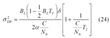
::[[File: MBOC_Eq_24.png|none| | ::[[File: MBOC_Eq_24.png|none|380px]] | ||
where <math>\alpha</math> is the slope of the autocorrelation function around the main peak. The above derived expressions are in consonance with the results obtained in [L. Ries et al., 2003]<ref>[L. Ries et al., 2003] L. Ries, F. Legrand, L. Lestarquit, W. Vigneau, J.L. Issler , Tracking and Multipath Performance Assessments of BOC Signals Using a Bit-Level Signal Processing Simulator, Proceedings of the International Technical Meeting of the Institute of Navigation, ION-GNSS 2003, 9-12 September, 2003, Oregon Convention Center, Portland, Oregon, USA.</ref> and [O. Julien, 2005] <ref name="OJ_2005"/> and confirm the fact that depending on the slope of the autocorrelation function of the signal waveform around the main peak, the tracking performance and achievable sensitivity will be better or worse, as we expected. Indeed, the steeper the autocorrelation function around the main peak is, the better the performance of the signal will be in terms of standard error. | where <math>\alpha</math> is the slope of the autocorrelation function around the main peak. The above derived expressions are in consonance with the results obtained in [L. Ries et al., 2003]<ref>[L. Ries et al., 2003] L. Ries, F. Legrand, L. Lestarquit, W. Vigneau, J.L. Issler , Tracking and Multipath Performance Assessments of BOC Signals Using a Bit-Level Signal Processing Simulator, Proceedings of the International Technical Meeting of the Institute of Navigation, ION-GNSS 2003, 9-12 September, 2003, Oregon Convention Center, Portland, Oregon, USA.</ref> and [O. Julien, 2005] <ref name="OJ_2005"/> and confirm the fact that depending on the slope of the autocorrelation function of the signal waveform around the main peak, the tracking performance and achievable sensitivity will be better or worse, as we expected. Indeed, the steeper the autocorrelation function around the main peak is, the better the performance of the signal will be in terms of standard error. | ||
| Line 255: | Line 255: | ||
We can see this more clearly if we recall the equations derived in the [[Composite BOC (CBOC)]] implementation of MBOC. Indeed, | We can see this more clearly if we recall the equations derived in the [[Composite BOC (CBOC)]] implementation of MBOC. Indeed, | ||
::[[File: MBOC_Eq_25.png|none| | ::[[File: MBOC_Eq_25.png|none|520px]] | ||
| Line 265: | Line 265: | ||
Finally, it is important to note that although MBOC(6,1,1/11) and BOC(1,1) present improved performance with respect to BPSK(1), the tracking region is smaller if we track the whole MBOC. In fact, the linear region around the main peak will be six times narrower. | Finally, it is important to note that although MBOC(6,1,1/11) and BOC(1,1) present improved performance with respect to BPSK(1), the tracking region is smaller if we track the whole MBOC. In fact, the linear region around the main peak will be six times narrower. | ||
==== Signal structure and DLL sensitivity ==== | ==== Signal structure and DLL sensitivity ==== | ||
| Line 272: | Line 273: | ||
Following [P. Ward, 1996]<ref>[P. Ward, 1996] P. Ward, Satellite Signal Acquisition and Tracking in Understanding GPS: Principles and Applications, Artech House Inc.</ref> and [O. Julien, 2005]<ref name="OJ_2005"/> to study the PLL sensitivity, the rule of thumb we will use is to have a 3-sigma of the errors within the linear tracking region, which is in theory <math>\pm \frac{\delta}{2}</math>. This can also be expressed as follows: | Following [P. Ward, 1996]<ref>[P. Ward, 1996] P. Ward, Satellite Signal Acquisition and Tracking in Understanding GPS: Principles and Applications, Artech House Inc.</ref> and [O. Julien, 2005]<ref name="OJ_2005"/> to study the PLL sensitivity, the rule of thumb we will use is to have a 3-sigma of the errors within the linear tracking region, which is in theory <math>\pm \frac{\delta}{2}</math>. This can also be expressed as follows: | ||
::[[File: MBOC_Eq_26.png|none| | ::[[File: MBOC_Eq_26.png|none|180px]] | ||
It must be noted that actually not all the errors are included in the expression above, and thus the multipath-induced tracking error must be studied separately. The reason for this is that the multipath error does not imply a tracking error in the sense that it would push the tracking loop away from its stability point as explained in detail in [O. Julien, 2005] <ref name="OJ_2005"/>. | It must be noted that actually not all the errors are included in the expression above, and thus the multipath-induced tracking error must be studied separately. The reason for this is that the multipath error does not imply a tracking error in the sense that it would push the tracking loop away from its stability point as explained in detail in [O. Julien, 2005] <ref name="OJ_2005"/>. | ||
| Line 278: | Line 279: | ||
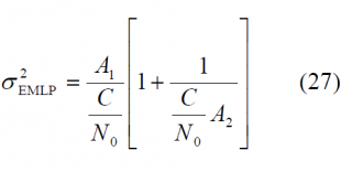
Recalling now the equations for the tracking error of (23) and (24) above, we can see that (23) can be simplified for the EMLP as follows: | Recalling now the equations for the tracking error of (23) and (24) above, we can see that (23) can be simplified for the EMLP as follows: | ||
::[[File: MBOC_Eq_27.png|none| | ::[[File: MBOC_Eq_27.png|none|320px]] | ||
where | where | ||
::[[File: MBOC_Eq_28.png|none| | ::[[File: MBOC_Eq_28.png|none|520px]] | ||
and | and | ||
::[[File: MBOC_Eq_29.png|none| | ::[[File: MBOC_Eq_29.png|none|490px]] | ||
| Line 298: | Line 299: | ||
with | with | ||
::[[File: MBOC_Eq_31.png|none| | ::[[File: MBOC_Eq_31.png|none|280px]] | ||
According to this, if we assume as mentioned above that <math>3\sigma_{\delta_{\tau},TH} \le \delta /2</math> for the case of the EMLP discriminator, the EMLP tracking threshold results to be: | According to this, if we assume as mentioned above that <math>3\sigma_{\delta_{\tau},TH} \le \delta /2</math> for the case of the EMLP discriminator, the EMLP tracking threshold results to be: | ||
::[[File: MBOC_Eq_32.png|none| | ::[[File: MBOC_Eq_32.png|none|380px]] | ||
and for the DP we have equally: | and for the DP we have equally: | ||
::[[File: MBOC_Eq_33.png|none| | ::[[File: MBOC_Eq_33.png|none|380px]] | ||
Using the expressions above, the tracking thresholds are computed in the next figures as a function of the coherent integration time and the DLL loop bandwidth. For the case of infinite bandwidth the expressions for the standard delay error simplify considerably adopting <math>A_1</math>,<math>A_2</math> and <math>A_3</math> the following values: | Using the expressions above, the tracking thresholds are computed in the next figures as a function of the coherent integration time and the DLL loop bandwidth. For the case of infinite bandwidth the expressions for the standard delay error simplify considerably adopting <math>A_1</math>,<math>A_2</math> and <math>A_3</math> the following values: | ||
::[[File: MBOC_Eq_34.png|none| | ::[[File: MBOC_Eq_34.png|none|240px]] | ||
::[[File: MBOC_Eq_35.png|none| | ::[[File: MBOC_Eq_35.png|none|240px]] | ||
::[[File: MBOC_Eq_36.png|none| | ::[[File: MBOC_Eq_36.png|none|180px]] | ||
| Line 403: | Line 404: | ||
The figures obtained above extend over very long coherent integrations. In fact, no data channel could in reality reach such values unless external sources were used, what shows clearly the superiority of the pilot channel for these purposes. Indeed, the introduction of pilot channels by Galileo and the modernized GPS can be considered as one of the main contributions to the navigation. Navigation and communication applications require of different needs and the use of pilot signals in GNSS in the future is clear proof of that. | The figures obtained above extend over very long coherent integrations. In fact, no data channel could in reality reach such values unless external sources were used, what shows clearly the superiority of the pilot channel for these purposes. Indeed, the introduction of pilot channels by Galileo and the modernized GPS can be considered as one of the main contributions to the navigation. Navigation and communication applications require of different needs and the use of pilot signals in GNSS in the future is clear proof of that. | ||
== MBOC Interference with other GNSSes == | == MBOC Interference with other GNSSes == | ||
Interoperability and compatibility have been hot issues in the design of Galileo since the beginning. Indeed, as more systems join the select club of countries with their own navigation system, the more important these concepts have become. As we have seen in chapter 2, the global system of systems that GPS, GLONASS, Galileo, the Japanese Quasi Zenith Satellite System (QZSS), the Chinese | Interoperability and compatibility have been hot issues in the design of Galileo since the beginning. Indeed, as more systems join the select club of countries with their own navigation system, the more important these concepts have become. As we have seen in chapter 2, the global system of systems that GPS, GLONASS, Galileo, the Japanese Quasi Zenith Satellite System (QZSS), the Chinese [[BeiDou_General_Introduction|BeiDou System (BDS)]] and the Indian Regional Navigation Satellite System (IRNSS) might become one day makes this chapter of major interest. | ||
As defined in, [S. Wallner et al., 2005] <ref name="SW_2005"> [S. Wallner et al., 2005] S. Wallner, G.W. Hein, J.-A. Avila Rodriguez, T. Pany, A. Posfay, Interference Computations Between GPS and Galileo, Proceedings of the International Technical Meeting of the Institute of Navigation, ION-GNSS 2005, 13-16 September, 2005, Long Beach, California, USA.</ref>and [S. Wallner et al., 2006]<ref>[S. Wallner et al., 2006b] S. Wallner, J.-A. Avila-Rodriguez, G.W. Hein, Interference Computations between Several GNSS Systems, ESA Navitec 2006, December 11-13, 2006, Noordwijk, The Netherlands.</ref> and, interoperability refers to the ability of civil U.S. and foreign space-based PNT services to be used together to provide better capabilities compared with those that would be achieved relying solely on one service or signal. | As defined in, [S. Wallner et al., 2005] <ref name="SW_2005"> [S. Wallner et al., 2005] S. Wallner, G.W. Hein, J.-A. Avila Rodriguez, T. Pany, A. Posfay, Interference Computations Between GPS and Galileo, Proceedings of the International Technical Meeting of the Institute of Navigation, ION-GNSS 2005, 13-16 September, 2005, Long Beach, California, USA.</ref>and [S. Wallner et al., 2006]<ref>[S. Wallner et al., 2006b] S. Wallner, J.-A. Avila-Rodriguez, G.W. Hein, Interference Computations between Several GNSS Systems, ESA Navitec 2006, December 11-13, 2006, Noordwijk, The Netherlands.</ref> and, interoperability refers to the ability of civil U.S. and foreign space-based PNT services to be used together to provide better capabilities compared with those that would be achieved relying solely on one service or signal. | ||
In June 2004, the United States and the European Union signed a historical Agreement on the common use of shared frequencies, setting up a complete methodology to assess the GPS/Galileo radio frequency compatibility. More details on the theoretical framework can be found in[[GNSS Interference Model]]. Based on the mathematical ideas gathered in the work, [S. Wallner et al., 2005] <ref name="SW_2005"/> have carried out simulations with smooth spectra and with real codes. According to the results, the degradation from [[GPS General Introduction|GPS]] on [[GALILEO General Introduction|Galileo]] and of Galileo on GPS is lower than 0.25 dB proving thus that both systems can perfectly coexist. Moreover, the introduction of [[QZSS]] will lead to an increase of the intersystem interference in the visibility region of QZSS that will never be higher than 0.07 dB. We show next the degradation values for BOC(1,1) when the analytical model is employed. | In June 2004, the United States and the European Union signed a historical Agreement on the common use of shared frequencies, setting up a complete methodology to assess the GPS/Galileo radio frequency compatibility. More details on the theoretical framework can be found in [[GNSS Interference Model]]. Based on the mathematical ideas gathered in the work, [S. Wallner et al., 2005] <ref name="SW_2005"/> have carried out simulations with smooth spectra and with real codes. According to the results, the degradation from [[GPS General Introduction|GPS]] on [[GALILEO General Introduction|Galileo]] and of Galileo on GPS is lower than 0.25 dB proving thus that both systems can perfectly coexist. Moreover, the introduction of [[QZSS]] will lead to an increase of the intersystem interference in the visibility region of QZSS that will never be higher than 0.07 dB. We show next the degradation values for BOC(1,1) when the analytical model is employed. | ||
::::[[File:MBOC_Fig_13.png|none|thumb|580px|'''''Figure 13: Maximum <math>C/N_0</math> Degradation due to Intersystem Interference caused by the GPS L1 Signals on Galileo [S. Wallner et al., 2005] <ref name="SW_2005"/> . Minimum: 0.186 dB, mean 0.214 dB and maximum 0.243 dB.]] | ::::[[File:MBOC_Fig_13.png|none|thumb|580px|'''''Figure 13: Maximum <math>C/N_0</math> Degradation due to Intersystem Interference caused by the GPS L1 Signals on Galileo [S. Wallner et al., 2005] <ref name="SW_2005"/> . Minimum: 0.186 dB, mean 0.214 dB and maximum 0.243 dB.]] | ||
| Line 430: | Line 432: | ||
==References== | ==References== | ||
<references/> | <references/> | ||
== Credits == | |||
The information presented in this NAVIPEDIA’s article is an extract of the PhD work performed by Dr. Jose Ángel Ávila Rodríguez in the FAF University of Munich as part of his Doctoral Thesis “On Generalized Signal Waveforms for Satellite Navigation” presented in June 2008, Munich (Germany) | |||
[[Category:Fundamentals]] | [[Category:Fundamentals]] | ||
[[Category:GNSS Signals]] | [[Category:GNSS Signals]] | ||
Latest revision as of 17:37, 8 September 2014
| Fundamentals | |
|---|---|
| Title | MBOC Modulation |
| Author(s) | J.A Ávila Rodríguez, University FAF Munich, Germany. |
| Level | Advanced |
| Year of Publication | 2011 |
MBOC modulation definition and analysis
Nearly twenty months after the EU and the US signed the Agreement on the Promotion, Provision and use of Galileo and GPS Satellite-Based Navigation Systems and Related Applications an optimized signal waveform named MBOC (Multiplexed Binary Offset Carrier modulation) was proposed by a common group of experts of the EU and US for GPS L1C and Galileo E1 OS [G.W. Hein et al., 2006a][1], [G.W. Hein et al., 2006b] [2] and [J.-A. Avila-Rodriguez et al., 2006d] [3].
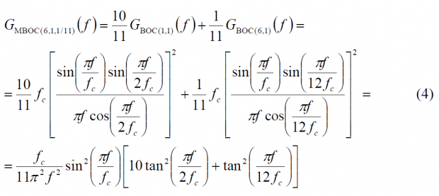
Except for the fact that the CBCS definition requires Interplex to multiplex all the signals, the MBOC modulation can be seen a particular case of the CBCS solution where the BCS sequence adopts the known sine-phased BOC-like form. In this sense, MBOC(6,1,1/11) could also be expressed as CBCS([1,-1,1,-1,1,-1,1,-1,1,-1,1,-1],1,1/11) if the requirement on the Interplex Multiplexing were abandoned. The main objective of the common GPS and Galileo signal design activity was that the PSD of the proposed solution would be identical for GPS L1C and Galileo E1 OS when the pilot and data components are computed together. This assures a high interoperability between both signals. This normalized (unit power) power spectral density, specified without the effect of band-limiting filters and payload imperfections, is given by
where the high BOC frequency component, that is BOC(6,1), is shown to be:
with [math]\displaystyle{ f_c = 1.023 MHz }[/math]. Equally, the low BOC frequency component, namely BOC(1,1) will be:
and thus:
Additional conclusions can be drawn from analysing the spectral shape of MBOC. Indeed, as shown in [J.-A. Avila-Rodriguez et al., 2006b][4] an ideal power spectral density regarding the tracking performance should be inversely proportional to the square of the frequency, according to (see CBCS Modulation):
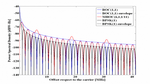
It must be noted that such a spectrum would have nevertheless other non-desirable properties with regards to its implementation. However, if we look now at the envelope of the well-known power spectral densities of BPSK(1) and BOC(1,1) we can clearly recognize that their envelopes interestingly decay with [math]\displaystyle{ 1/f^2 }[/math], as Figure 1 shows next. Moreover, MBOC seems to follow pretty well this desirable pattern too. In fact, this was one of the figures in the mind of all those people involved in the optimization of the Galileo OS in E1.
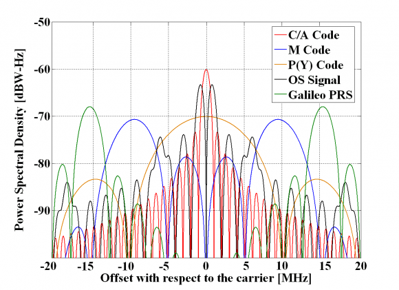
We show in the next figure all the Galileo and GPS signals in the E1/L1-band.
Implementing MBOC
Once we have defined the power spectral density of MBOC, it is the right moment to talk about the implementation. Indeed, different time representations result in the same power spectral density and the Agreement between the EU and the US on MBOC left this freedom to both parties so that each could implement its own solution according to its own conception. Two solutions have been realized to implement MBOC:
- CBOC: The Composite BOC is the solution adopted by Galileo for the Open Service in E1/L1. It is an Interplex multiplexing where the sub-carriers BOC(1,1) and BOC(6,1) are added in anti-phase on each channel.
- TMBOC: The Time-Multiplexed BOC is the solution adopted by GPS for L1C. It is a binary signal where BOC(1,1) and BOC(6,1) are time-multiplexed according to a pre-established pattern that was optimized to improve the correlation properties of the signal when the effect of the PRN code is taken into account.
It is interesting to mention that between CBCS and the final MBOC(6,1) there was an intermediate solution that was object of interest for a short period of time. This was the so called MBOC(4,1).
One final but important comment is related to the power allocated on the high frequency component of MBOC, namely BOC(6,1). Indeed, the 1/11 of power refers to the power at generation, without accounting for the effect of the satellite’s filter and other imperfections. This is so because as we know, MBOC admits different implementations, being one of them TMBOC. If we would define the exact power split at user level, the power at generation would be different depending on the final implementation. TMBOC accomplishes the required power percentage by time-multiplexing BOC(6,1) and BOC(1,1) so that 1/11 of the time the satellite transmits BOC(6,1) and the rest of the time BOC(1,1). Since the GPS L1C codes have a length of 10,230 chips, this percentage incorporates the factorial decomposition of 10,230. It is trivial to show that and indeed 11 was found to be the optimum number to divide the transmission periods of the multiplexing signals of GPS L1C. Indeed, 1/11 of the time was long enough to considerably improve the performance with respect to BOC(1,1) but not so long to concentrate too much power on the high frequencies and overlap the M-Code and PRS to non acceptable levels.
Finally, it is important to mention that in the case of CBOC, the generation of power presents no limitations since this is achieved by correspondingly modulating the amplitude.
On MBOC and Antisymmetric sequences
Before we describe the performance of MBOC regarding the characteristics and details of its different implementations, let us first make some final comments on the MBOC spectrum and the ideas behind.
MBOC implementation ( CBOC) is the result of an additive and subtractive mixture of two separate spreading symbols. Moreover, we have already noted that some Binary Coded Symbols (BCS) sequences can potentially cause tracking bias in receivers adapted to receive only one of the spreading symbols. This was indeed one of the main disadvantages of CBCS. The solution to this problem was given by MBOC and the key concept is antisymmetric sequences. Since BOC(1,1) is antisymmetric, receiver biases can be avoided by choosing the correct properties for the partner spreading symbol sequence.
Compatibility with BOC(1,1) receivers was a major driver in the design of the optimized Galileo signal. As a result of this, having BOC(1,1) a partner spreading symbol sequence with zero cross-correlation became one of the most important drivers in the design of the Galileo OS in E1.
After CBCS was proposed, a new BCS solution that could avoid all the CBCS modulations drawbacks was the objective of the works of US and EU. We can summarize the properties that this desired BCS sequence should present:
- Anti-symmetry
- Balance (zero-sum) for the sequence
- Zero crosscorrelation with the partner sequence
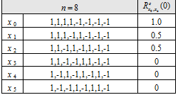
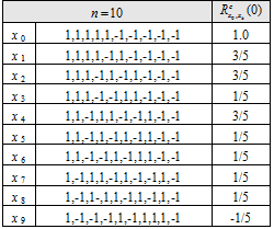
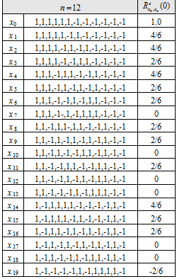
As shown in [A.R. Pratt et al., 2006][5] a comprehensive search for binary sequences was conducted with some or all of these properties. These are listed below for a variety of sequence lengths [math]\displaystyle{ n }[/math], all divisible by 2, from 2 to 12. Moreover, we show only distinct sequences so that the tables contain [math]\displaystyle{ {x_i} }[/math] but not the time reversed versions [math]\displaystyle{ \left \{-x_i\right \}, \left \{x_{n-1-i}\right \} or \left \{-x{n-1-i} \right \} }[/math]. Since the sequences are antisymmetric, they may be considered to be constructed from a base sequence [math]\displaystyle{ \left \{ \hat y \right \} }[/math] of length [math]\displaystyle{ n }[/math] as shown in the following equation:
All antisymmetric sequences, of even length [math]\displaystyle{ n }[/math] are balanced. The next tables show the cross-correlation with a BOC(1,1) partner sequence, under the assumption that the spreading symbol durations are common, that is the duration of an sequence is identical with that of an sequence, for example.
Moreover, the cross-correlation between [math]\displaystyle{ x_0 = BOC(1,1) }[/math] and the corresponding [Binary Coded Symbols (BCS) |BCS sequence]] [math]\displaystyle{ x_k }[/math] is shown to be:
where "mod" represents the modulo operation.
Tables of Distinct Spreading Symbol Sequences for n=2 to 12
From the tables, it can be seen that only tables for , that is , have any entries with zero crosscorrelation with BOC(1,1). For , there is only 1 sequence corresponding to a BOC(2,1) spreading symbol modulation. For , there are 3 permissible sequences, [math]\displaystyle{ x_3,x_4,x_5 }[/math]. Of these, [math]\displaystyle{ x_4 }[/math] corresponds to the BOC(4,1) modulation. Finally for , there are 6 possible sequences, [math]\displaystyle{ x_7,x_{10},x_{13}, x_{17},x_{18} }[/math] where [math]\displaystyle{ x_{17} }[/math] corresponds to BOC(6,1), one of the solutions and indeed the best in terms of performance.
MBOC Tracking Sensitivity
As shown in [O. Julien, 2005] [6], we can distinguish two types of tracking sensitivity:
- Code Tracking Sensitivity (DLL)
- Carrier Tracking Sensitivity (PLL)
We describe the MBOC properties regarding Code Tracking sensitivity in detail.
Code Tracking Sensitivity
Following the definition from [O. Julien, 2005][6], the tracking sensitivity can be defined as the minimum pre-correlation Signal to Noise Ratio (SNR) that is necessary to correctly track a desired signal. To correctly track, the post-correlation SNR should be as high as possible, what can be achieved by different means. Whatever the followed approach is, the main objective is always to increase the correlation gain, which is the ratio between the post-correlation SNR and pre-correlation SNR.
According to [O. Julien, 2005][6], the post-correlation [math]\displaystyle{ SNR_{post} }[/math] is shown to be
where
- [math]\displaystyle{ \varepsilon_{\tau} }[/math] is the code delay
- [math]\displaystyle{ \tilde{R} }[/math] is the correlation of the filtered incoming signal with the local replica
- [math]\displaystyle{ N_0 }[/math] is the noise power density
- [math]\displaystyle{ P }[/math] is the power of the desired signal
- and [math]\displaystyle{ T_I }[/math] is the coherent integration time.
On the other hand, the pre-correlation SNR adopts the following form:
where [math]\displaystyle{ \beta_r }[/math] is the pre-correlation bandwidth.
Therefore the correlation gain can be expressed as [R. Watson, 2005][7]
which can be further simplified to
as also shown in [O. Julien, 2005] [6].
Effect of longer integrations on code tracking sensitivity
If we take a closer look into the expressions above, we can clearly see that the most straightforward way of improving the tracking sensitivity is to increase the coherent integration [math]\displaystyle{ T_I }[/math] as much as possible. Unfortunately, this is not always possible due to the presence of data bits or secondary codes. Additionally, even though it were possible to integrate for long periods of time in the absence of data, other major problems coming from the code and phase delay variation during the integration would appear.
The best known solution to overcome this problem is the use of standard non-coherent summations according to the following expression
where [math]\displaystyle{ I_k }[/math] and [math]\displaystyle{ Q_k }[/math] correspond to the in-phase and quadrature non-coherent correlation inputs obtained over a coherent integration time [math]\displaystyle{ T_I }[/math]. Moreover M is the number of values used for the non-coherent integration and [math]\displaystyle{ Y_{st} }[/math], as defined in (12) can be used to apply the Neumann-Pearson lemma, as this lemma allows one to obtain a powerful test in the case of two simple alternative hypotheses [math]\displaystyle{ H_1 }[/math] and [math]\displaystyle{ H_2 }[/math].
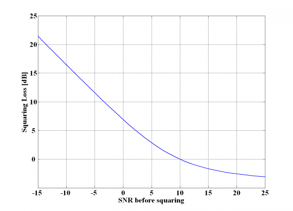
By doing so, further correlation gain can be reached but due to the squaring in the expression above the process is subject to the so-called squaring losses that reduce the total gain [M.M. Chansarkar and L. Garin, 2000][8] and [G.D. MacGougan, 2003][9]. The squaring loss depends on the SNR before the non-coherent integration is realized and is higher the lower the SNR. Thus, long coherent integration is desirable before the non-coherent correlation is applied, in order to reach a good SNR before accumulating. Indeed, by non-coherent integrating we increase the power of our desired signal but since the noise is not eliminated as with the coherent integration, the gain in power is lower than the increase of noise.
According to this scheme, depending on whether the desired signal is or is not present in the searching bin, the variable Zk will present a Ricean or Rayleigh distribution correspondingly. Indeed, it can be shown that if the desired signal is present, a Ricean distribution holds, which has the following probability density function [J.-A. Avila-Rodriguez et al., 2006b][4]:
where z is the test variable, A is the signal amplitude, [math]\displaystyle{ \sigma^2 }[/math] the noise power and [math]\displaystyle{ I_0\left ( \right ) }[/math] the zero-order modified Bessel function of the first kind. According to this, if the output SNR is defined as:
where
the squaring loss can be obtained according to [G. Lachapelle, 2004] [10] as follows:
as shown graphically in the following figure:
Reading the squaring losses from the figure above, the total processing gain with respect to the pre-correlation SNR can be easily calculated [J.-A. Avila-Rodriguez et al., 2006b][4]:
where
- [math]\displaystyle{ G }[/math] is the total processing gain (dB) with respect to the pre-correlation SNR,
- [math]\displaystyle{ G_{NC} }[/math] is the non-coherent signal gain from the non-coherent integration alone,
- [math]\displaystyle{ \beta_r }[/math] is the pre-detection bandwidth,
- [math]\displaystyle{ T_I }[/math]is the total coherent integration time,
- [math]\displaystyle{ M }[/math] is the number of non-coherent integrations,
- and [math]\displaystyle{ S_L }[/math] are the squaring losses that we defined above.
The main drawback from the standard non-coherent integration comes from the fact that the noise is squared. Alternative expressions have been studied in the literature to sort out this problem as explained in [J.-A. Avila-Rodriguez et al., 2005c][11] and [G. Lachapelle, 2004] [10]. One of those is the non-coherent differential correlation dc, also known as dot-product correlation, which is based on multiplying consecutive samples. One of its multiple expressions is:
where [math]\displaystyle{ I_i }[/math] and [math]\displaystyle{ Q_i }[/math] denote again the output of the coherent integration process. Since now the input i is multiplied with the input i-1, better results are expected in the ideal case, given that the noise is uncorrelated in the time with itself. This is in fact what the simulations show. However, this algorithm presents a main drawback due to its high sensitivity to Doppler.
In the previous lines we have briefly discussed the most straightforward way of increasing tracking sensitivity by increasing the total integration time. Additionally, there exist other ways of increasing the post-correlation SNR such as increasing the signal power at the satellite. Unfortunately, this would have extremely negative effects on interference with already existing terrestrial systems.
Signal structure and DLL code tracking error
Fortunately, there is another way of increasing the per se tracking sensitivity of a receiver, which is based on the signal structure of the desired signal. As we know, any DLL configuration is usually based on the combination of early and late correlators, so that the noise correlation of each output is also important to the resulting combined noise. Here plays the signal structure an outstanding role since the DLL tracking sensitivity will be affected by the selection of the signal waveform. In the next lines, we will show the theoretical tracking performance of MBOC and we will compare it with that of BOC(1,1) and the C/A Code.
If perfect normalization is assumed and the loop bandwidth is negligible compared with the bandwidth of the discriminator noise, [J.K. Holmes, 2000][12] and [O. Julien, 2005][6]: have shown that the DLL estimated code delay tracking error variance with Gaussian noise yields:
where
- [math]\displaystyle{ disc }[/math] refers to the type of discriminator,
- [math]\displaystyle{ S_{N_{disc}} }[/math] is the discriminator noise PSD,
- [math]\displaystyle{ B_L }[/math] is the loop bandwidth,
- [math]\displaystyle{ T_I }[/math] TI is the integration time, and
- [math]\displaystyle{ K_{disc} }[/math] is the loop gain associated to the discriminator, with [math]\displaystyle{ K_{disc} = \frac {dD_{disc}}{d\varepsilon_{\tau}} \Bigg | _{ \delta_ \tau = 0} }[/math], where [math]\displaystyle{ D_{disc} }[/math] is the discriminator function.
Additionally, since the noise power spectral density that results from multiplying the incoming signal with the local replica is very wide band, we can approximate the expression above by the following [O. Julien, 2005] [6]:
where [math]\displaystyle{ \sigma^2_{D_{disc}} }[/math] represents the discriminator output standard deviation without normalizing. This expression is very close to that of the PLL, with the difference that the effect of the normalization (through [math]\displaystyle{ K_{disc} }[/math]) has been introduced here. This means in other words, that the DLL tracking error is directly dependent upon the discriminator resistance to noise, and thus on the signal structure.
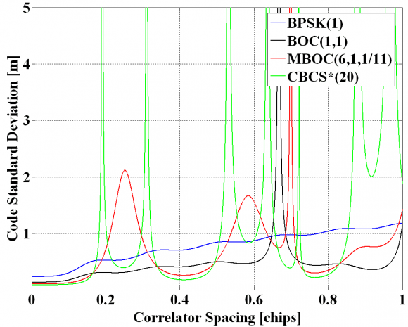
If perfect normalization is assumed again, no frequency uncertainty is considered, a front-end filter with ideal unity gain and receiver bandwidth [math]\displaystyle{ \beta_r }[/math] and a code delay error remaining small, the DLL tracking error variance produced by use of an EMLP discriminator is shown to be [O. Julien, 2005] [6] and [J.W. Betz and K.R. Kolodziejski, 2000] [13]:
where [math]\displaystyle{ \beta_r }[/math] is the receiver bandwidth and [math]\displaystyle{ \delta }[/math]the correlator spacing of the receiver.
In the figure above, derived according to [J.W. Betz and K.R. Kolodziejski, 2000] [13], a receiver bandwidth [math]\displaystyle{ \beta_r }[/math] of 24 MHz, a loop bandwidth [math]\displaystyle{ B_L }[/math] of 1 Hz, a [math]\displaystyle{ C/N_0 }[/math] of 45 dB-Hz and a coherent integration time [math]\displaystyle{ T_I }[/math] of 4 ms were used for BOC(1,1) and MBOC(6,1,11). For BPSK(1), 20 ms coherent integration were assumed. It is important to note that other alternative models have been derived to describe the behaviour of the code tracking noise for spacing values close to zero as shown in [T. Pany et al., 2002][14]. In addition, similar figures could also be obtained for different receiver discriminators. One final comment on the figure above is that MBOC has got less dangerous regions than CBCS* regarding the code spacing what was also an important advantage in favour of MBOC.
Equally, as derived in [O. Julien, 2005] [6], the DLL tracking error variance using a Dot Product (DP) discriminator presents the following expression:
which simplifies for the case that an infinite receiver bandwidth is assumed, yielding:
where [math]\displaystyle{ \alpha }[/math] is the slope of the autocorrelation function around the main peak. The above derived expressions are in consonance with the results obtained in [L. Ries et al., 2003][15] and [O. Julien, 2005] [6] and confirm the fact that depending on the slope of the autocorrelation function of the signal waveform around the main peak, the tracking performance and achievable sensitivity will be better or worse, as we expected. Indeed, the steeper the autocorrelation function around the main peak is, the better the performance of the signal will be in terms of standard error.
Additionally, we can see from the expressions above that if an infinite front-end filter bandwidth is assumed, the squaring losses for the Dot Product (DP) discriminator do not depend on the signal structure any more, while for case of the Early Minus Late Power (EMLP) discriminator they do depend, being these larger the steeper the autocorrelation function around the main peak.
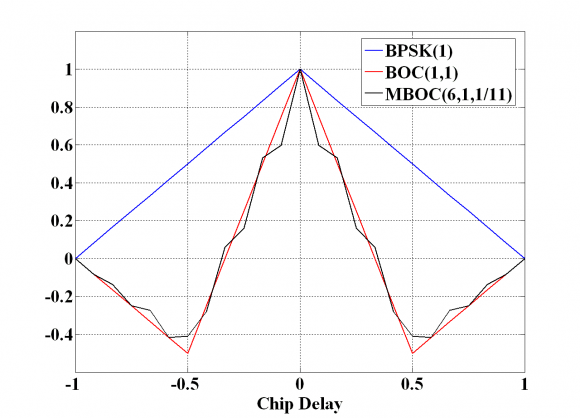
If we take a look now at Figure 5 next, we can recognize that while the GPS C/A code presents a slope value of [math]\displaystyle{ \alpha = 1 }[/math], for BOC(1,1) the slope around the main peak is of [math]\displaystyle{ \alpha = 3 }[/math], resulting thus in an improvement of the tracking error standard deviation of 2.4 dB approximately (without accounting for the squaring effects).
The improvement is still more spectacular if we take a look at the MBOC autocorrelation function, where the average slope around the main peak, considering data and pilot together, is shown to be 53/11. This represents an improvement of the tracking performance of approximately 1.03 dB with respect to BOC(1,1) and of 3.41 dB with respect to BPSK(1). The slope of the main peak can be easily computed from (1).
In fact, the slope of the autocorrelation function of BOC(6,1) takes a value of 23 around the main peak for infinite bandwidth. Equally, for BOC(1,1) the slope has a value 3 and the resulting slope of MBOC around the main peak will be . In general, the slope of the main peak of a BOC(x,1) is shown to be for the case of infinite bandwidth. It is important to note that the MBOC ACF shown above (CBOC implementation) corresponds to the mean ACF that results from averaging the data and pilot channel. In the case that both data and pilot would alternate the phase of the BOC(6,1) signal every chip, a similar result could be obtained. For the TMBOC case, it would represent the case when BOC(6,1) is on both data and pilot with the same power on both. This is equivalent to saying that the cross-correlation between BOC(1,1) and BOC(6,1) does not show up in the figures above since they average to zero.
We can see this more clearly if we recall the equations derived in the Composite BOC (CBOC) implementation of MBOC. Indeed,
so that the cross-term between the BOC(1,1) and BOC(6,1) does not appear in the expression, unlike for the and cases.
If we take a look now into the performance of the data and pilot channels separately, we can see that for the case of GPS L1C, the TMBOC implementation of MBOC puts all the high frequency power on the pilot channel for tracking purposes. This results in a steeper slope of the autocorrelation function around the main peak. Recalling the GPS power split between data and pilot of 25/75 in L1C, the slope will have a value of , bringing thus an improvement for the pilot channel of approximately 3.67 dB with respect to BPSK(1) and of 1.28 dB with respect to BOC(1,1). On the other hand, the data channel will present a performance equivalent to that of BOC(1,1).
Equivalently, its counterpart Galileo will have a performance 3.41 dB better than BPSK(1) and will be 1.03 dB better than BOC(1,1) since BOC(6,1) is placed on both data an pilot with a power split 50/50. This can also be seen if we take a look at the ACFs of the data and pilot channels separately.
Finally, it is important to note that although MBOC(6,1,1/11) and BOC(1,1) present improved performance with respect to BPSK(1), the tracking region is smaller if we track the whole MBOC. In fact, the linear region around the main peak will be six times narrower.
Signal structure and DLL sensitivity
Now that we have calculated the code tracking error for MBOC and the rest of Open signals in E1, the next step is to obtain the necessary [math]\displaystyle{ C/N_0 }[/math] to ensure a correct tracking. This will give us an idea of the potential DLL sensitivity of the different analysed signal structures.
Following [P. Ward, 1996][16] and [O. Julien, 2005][6] to study the PLL sensitivity, the rule of thumb we will use is to have a 3-sigma of the errors within the linear tracking region, which is in theory [math]\displaystyle{ \pm \frac{\delta}{2} }[/math]. This can also be expressed as follows:
It must be noted that actually not all the errors are included in the expression above, and thus the multipath-induced tracking error must be studied separately. The reason for this is that the multipath error does not imply a tracking error in the sense that it would push the tracking loop away from its stability point as explained in detail in [O. Julien, 2005] [6].
Recalling now the equations for the tracking error of (23) and (24) above, we can see that (23) can be simplified for the EMLP as follows:
where
and
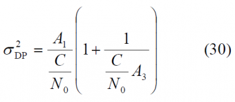
Equally for the Dot Product Discriminator, (24) can also be expressed as:
with
According to this, if we assume as mentioned above that [math]\displaystyle{ 3\sigma_{\delta_{\tau},TH} \le \delta /2 }[/math] for the case of the EMLP discriminator, the EMLP tracking threshold results to be:
and for the DP we have equally:
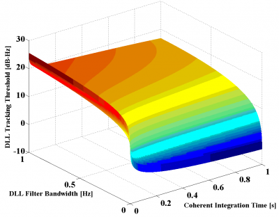
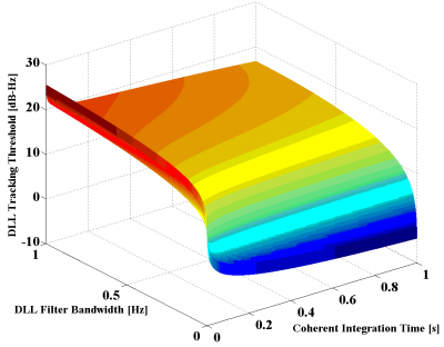
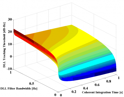
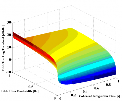
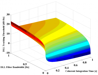
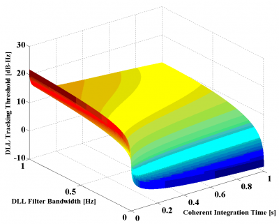
Using the expressions above, the tracking thresholds are computed in the next figures as a function of the coherent integration time and the DLL loop bandwidth. For the case of infinite bandwidth the expressions for the standard delay error simplify considerably adopting [math]\displaystyle{ A_1 }[/math],[math]\displaystyle{ A_2 }[/math] and [math]\displaystyle{ A_3 }[/math] the following values:
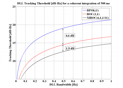
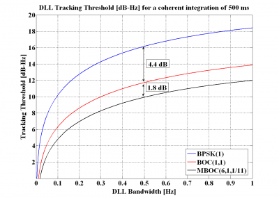
For comparison, a spacing of 0.1 chips (left) and a spacing of 0.2 chips (right) will be used.
Figure 6: DLL Tracking Threshold of BPSK(1) for the DP Discriminator
Figure 7: DLL Tracking Threshold of BOC(1,1) for the DP Discriminator
Figure 8: DLL Tracking Threshold of MBOC(6,1,1/11) for the DP
As we can recognize, using a chip spacing of 0.1 or 0.2 chips does not really make a big difference.
If we take a close look at the results shown in the figures above, we can see that MBOC presents the lowest tracking threshold and thus the best sensitivity, followed by BOC(1,1) and BPSK(1). It is also interesting to see that the results of the simulations show an even higher improvement of the [math]\displaystyle{ C/N_0 }[/math] sensitivity of MBOC with respect to BOC(1,1) and BPSK(1) than that predicted in the section “Signal structure and DLL code tracking error”. Indeed, while we saw there that MBOC was expected to have a tracking threshold 1 dB lower than that of BOC(1,1) and 3.4 dB better with respect to BPSK(1), the results of the figures above account for higher improvements. This could be due to filtering effects in the loop bandwidth and coherent integration that are not reflected in the analytical expressions for infinite bandwidth and that would positively favour MBOC against the other studied options.
Another important comment is that for the simulation of MBOC, a slope of 53/11 was assumed around the main peak. This is actually the average of data and pilot as we saw above. If we concentrate on the pilot performance of GPS L1C, the slope will be steeper since it has all the BOC(6,1) contribution, and even better results are expected.
In order to be able to compare the three signals more efficiently, the next figures show again the tracking thresholds for specific DLL configurations and chip spacing values.
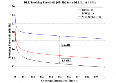
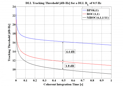
Figure 9: Figure 9: DLL tracking threshold for the DP Discriminator with a DLL loop bandwidth of 0.5 Hz and a chip spacing of [math]\displaystyle{ \delta =0.1 }[/math] (left) and [math]\displaystyle{ \delta =0.2 }[/math] (right).
It is interesting to note that for a coherent integration time of 0.5 seconds and a spacing of 0.1 chips, the improvement in sensitivity of BOC(1,1) and MBOC(6,1,1/11) with respect to BPSK(1) is even more spectacular. Indeed, BOC(1,1) performs approximately 4.6 dB better than BPSK(1), while MBOC outperforms BPSK(1) by 6.5 dB.
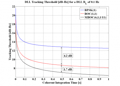
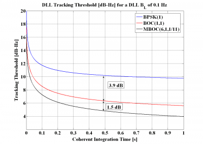
If we repeat the figures above for a DLL loop bandwidth of 0.1 Hz, we can see that although the difference in sensitivity of the various signals reduces, for a coherent integration of 0.5 seconds and a spacing of 0.1 chips, BOC(1,1) is still 4.2 dB better than BPSK(1) and MBOC(6,1,1/11) approximately 1.7 dB better than BOC(1,1).
Figure 10: DLL tracking threshold for the DP Discriminator with a DLL loop bandwidth of 0.1 Hz and a chip spacing of [math]\displaystyle{ \delta =0.1 }[/math] (left) and [math]\displaystyle{ \delta =0.2 }[/math] (right).
Once the sensitivity performance of the different signals has been compared as a function of the DLL loop bandwidth and the spacing, the next step is to assess the behaviour of these signals as a function of the coherent integration time.
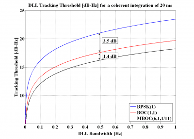
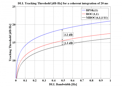
Figure 11: DLL tracking threshold for the DP Discriminator with a coherent integration time of 20 ms and a chip spacing of [math]\displaystyle{ \delta =0.1 }[/math] (left) and [math]\displaystyle{ \delta =0.2 }[/math] (right).
As we can see, for a DLL loop bandwidth of 0.5 Hz and a chip spacing of 0.1, BOC(1,1) has a sensitivity approximately 3.5 dB higher than that of BPSK(1) while MBOC(6,1,1/11) is better than BOC(1,1) by 1.4 dB.
Figure 12: DLL tracking threshold for the DP Discriminator with a coherent integration time of 500 ms and a chip spacing of [math]\displaystyle{ \delta =0.1 }[/math] (left) and [math]\displaystyle{ \delta =0.2 }[/math] (right).
Furthermore, when the coherent integration time is increased to 500ms, the sensitivity improvement of BOC(1,1) turns to be even clearer, resulting in a improvement of approximately 4.6 dB for BOC(1,1) with respect to BPSK(1) and of 1.9 dB for MBOC with respect to BOC(1,1).
From the figures above we can clearly recognize that the tracking threshold decreases as the integration time increases and the DLL loop bandwidth decreases. We can also see that the obtained values seem to be very low compared to those obtained in real applications. However, it must be noted that ideal conditions were assumed in the simulations.
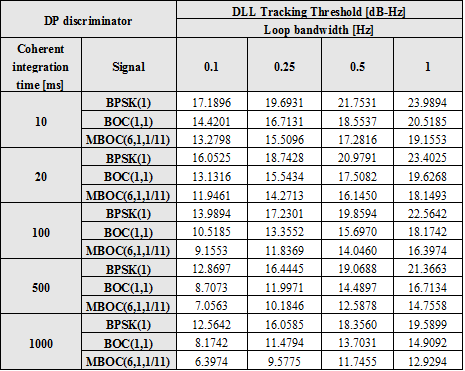
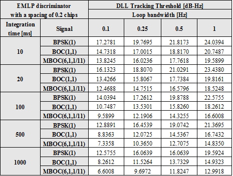
The following tables summarize the results for a chip spacing of 0.1 chips with DP and EMLP discriminators. Similar tables could have also been derived for a spacing of 0.2 chips showing always the superiority of MBOC against BOC(1,1) and C/A Code.
Once we have computed the DLL tracking threshold for the case of infinite bandwidth, the next step should be to employ different assumptions on the receiver bandwidth. Different configurations have been analysed delivering however similar results to those provided in previous lines.
The previous results show the ideal sensitivity values when all the potential sources of error are eliminated. As we know, increasing the total integration time does not only require extra complexity but implies other real challenges. Indeed, there are several problems inherent to longer coherent integration times, which are mainly related to the fact that the longer the coherent integration is, the more likely it will be that the signal conditions change during the integration period. Among others, the existence of frequency errors, non-ideal normalizations in the discriminator and the change of signal power during the integration would be the main sources of additional errors. They were not considered in the simulations above, since we are interested here in finding the theoretical limit, no matter how this is realized in reality. The same comment applies for the normalization of the discriminator. In fact, as explained in [O. Julien, 2005] [6], the effect of normalization in the discriminator would be another factor to take into account for more realistic simulations.
The figures obtained above extend over very long coherent integrations. In fact, no data channel could in reality reach such values unless external sources were used, what shows clearly the superiority of the pilot channel for these purposes. Indeed, the introduction of pilot channels by Galileo and the modernized GPS can be considered as one of the main contributions to the navigation. Navigation and communication applications require of different needs and the use of pilot signals in GNSS in the future is clear proof of that.
MBOC Interference with other GNSSes
Interoperability and compatibility have been hot issues in the design of Galileo since the beginning. Indeed, as more systems join the select club of countries with their own navigation system, the more important these concepts have become. As we have seen in chapter 2, the global system of systems that GPS, GLONASS, Galileo, the Japanese Quasi Zenith Satellite System (QZSS), the Chinese BeiDou System (BDS) and the Indian Regional Navigation Satellite System (IRNSS) might become one day makes this chapter of major interest.
As defined in, [S. Wallner et al., 2005] [17]and [S. Wallner et al., 2006][18] and, interoperability refers to the ability of civil U.S. and foreign space-based PNT services to be used together to provide better capabilities compared with those that would be achieved relying solely on one service or signal.
In June 2004, the United States and the European Union signed a historical Agreement on the common use of shared frequencies, setting up a complete methodology to assess the GPS/Galileo radio frequency compatibility. More details on the theoretical framework can be found in GNSS Interference Model. Based on the mathematical ideas gathered in the work, [S. Wallner et al., 2005] [17] have carried out simulations with smooth spectra and with real codes. According to the results, the degradation from GPS on Galileo and of Galileo on GPS is lower than 0.25 dB proving thus that both systems can perfectly coexist. Moreover, the introduction of QZSS will lead to an increase of the intersystem interference in the visibility region of QZSS that will never be higher than 0.07 dB. We show next the degradation values for BOC(1,1) when the analytical model is employed.
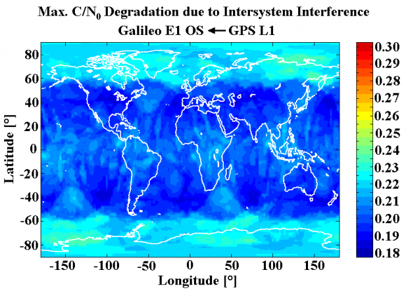 Figure 13: Maximum [math]\displaystyle{ C/N_0 }[/math] Degradation due to Intersystem Interference caused by the GPS L1 Signals on Galileo [S. Wallner et al., 2005] [17] . Minimum: 0.186 dB, mean 0.214 dB and maximum 0.243 dB.
If the same model is applied to the MBOC baseline, we can see that this contributes to an easier compatibility since the interference reduces in all considered scenarios. In fact, for average scenarios the typical figures are far lower than the 0.25 dB mentioned above.
The additional reduction of interference that MBOC provides is direct consequence of the better Spectral Separation Coefficients (SSC) of the signal. This confirms the great importance of this instrument to assess the degradation and overlapping among different signals. In the next figure we show the reduction of the maximum [math]\displaystyle{ C/N_0 }[/math] degradation that resulted from changing the baseline from BOC(1,1) to the final MBOC(6,1,1/11).
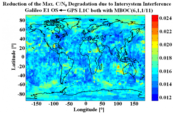 Figure 14: Reduction of the maximum [math]\displaystyle{ C/N_0 }[/math] Degradation due to Intersystem Interference when MBOC is used instead of BOC(1,1) [S. Wallner et al., 2005] [17] . Minimum: 0.016 dB, mean 0.018 dB and maximum 0.023 dB.
Equally, if we include the effect of QZSS, the following results are obtained.
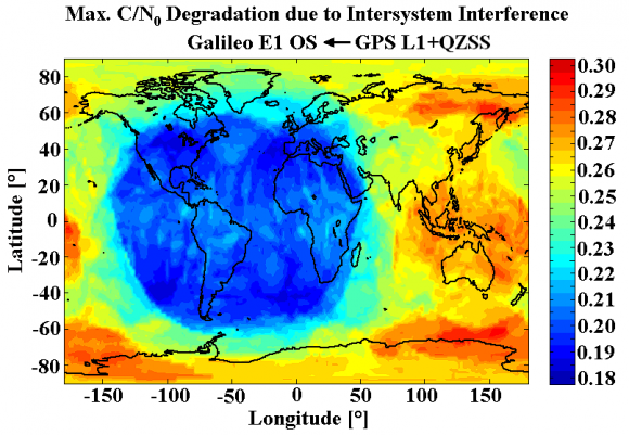 Figure 15: Maximum [math]\displaystyle{ C/N_0 }[/math] Degradation due to Intersystem Interference caused by the GPS L1 and QZSS Signals on Galileo [S. Wallner et al., 2005] [17]. Minimum: 0.187 dB, mean 0.247 dB and maximum 0.310 dB.
The mathematical framework of the methodology described in GNSS Interference Model can be easily expanded to other bands as for example E5-L5 or to other SBAS systems as done in [S. Wallner et al., 2005] [17] where the results with smooth spectra and real codes were compared. One final comment on the figures above is that the minimum power levels were used for the simulations resulting thus in significantly higher values of interference than those we will observe in a typical scenario. Nonetheless, it must be kept in mind that the purpose of an interference methodology is to assess compatibility in all the cases, and therefore looking at the worst cases is thus of major interest.
References
- ^ [G.W. Hein et al., 2006a] G. W. Hein, J.-A. Avila-Rodriguez, S. Wallner, A.R. Pratt, J.I.R. Owen, J.-L Issler, J.W. Betz, C.J. Hegarty, S. Lenahan, J.J. Rushanan, A.L. Kraay, T.A. Stansell, MBOC: The New Optimized Spreading Modulation Recommended for Galileo L1 OS and GPS L1C, Proceedings of the International Technical Meeting of the Institute of Navigation, IEEE/ION PLANS 2006, 24-27 April, 2006, Loews Coronado Bay Resort, San Diego, California, USA.
- ^ [G.W. Hein et al., 2006b] G. W. Hein, J.-A. Avila-Rodriguez, S. Wallner, A.R. Pratt, J.I.R. Owen, J.-L Issler, J.W. Betz, C.J. Hegarty, S. Lenahan, J.J. Rushanan, A.L. Kraay, T.A. Stansell, MBOC: The New Optimized Spreading Modulation Recommended for Galileo L1 OS and GPS L1C, Inside GNSS – Working Papers, Vol.1, No.4, May/June 2006, pp.57-65.
- ^ [J.-A. Avila-Rodriguez et al., 2006d] J.-A. Avila-Rodriguez, G. W. Hein, S. Wallner, A.R. Pratt, J.I.R. Owen, J.-L Issler, J.W. Betz, C.J. Hegarty, S. Lenahan, J.J. Rushanan, A.L. Kraay, T.A. Stansell, MBOC: The New Optimized Spreading Modulation Recommended for Galileo E1 OS and GPS L1C, ESA Navitec 2006, 11-13 December, 2006, Noordwijk, The Netherlands.
- ^ a b c [J.-A. Avila-Rodriguez et al., 2006b] J.-A. Avila-Rodriguez, T. Pany, G.W. Hein, Bounds on Signal Performance Regarding Multipath-Estimating Discriminators, Proceedings of the International Technical Meeting of the Institute of Navigation, ION-GNSS 2006, 26-29 September, 2006, Fort Worth Convention Center, Fort Worth, Texas, USA.
- ^ [A.R. Pratt et al., 2006] A.R. Pratt, J.I.R. Owen, G.W. Hein, J.-A. Avila-Rodriguez: Tracking Complex Modulation Waveforms- How to Avoid Receiver Bias, Proceedings of the International Technical Meeting of the Institute of Navigation, IEEE/ION PLANS 2006, 24-27 April, 2006, Loews Coronado Bay Resort, San Diego, California, USA.
- ^ a b c d e f g h i j k l [O. Julien, 2005] Olivier Julien, Design of Galileo L1F Receiver Tracking Loops, PhD Thesis, Department of Geomatics Engineering, University of Calgary
- ^ [R. Watson, 2005] R. Watson, High-Sensitivity GPS L1 Signal Analysis for Indoor Channel Modeling, Master’s thesis, Department of Geomatics Engineering, University of Calgary, UCGE Report 20216.
- ^ [M.M. Chansarkar and L. Garin, 2000] M.M. Chansarkar and L. Garin, Acquisition of GPS Signals at Very Low Signal to Noise Ratios, Proceedings of the National Technical Meeting of the Institute of Navigation, ION-NTM 2000, pp. 731-737, January 26-28, 2000, Anaheim, California, USA.
- ^ [G.D. MacGougan, 2003] G.D. MacGougan, High Sensitivity GPS Performance Analysis in Degraded Signal Environment, Master’s thesis, Department of Geomatics Engineering, University of Calgary, UCGE Report 20176.
- ^ a b [G. Lachapelle, 2004] Lachapelle, G., NAVSTAR GPS: Theory and Applications, ENGO 625 Lecture Notes, Department of Geomatics Engineering, University of Calgary.
- ^ [J.-A. Avila-Rodriguez et al., 2005c] J.-A. Avila-Rodriguez, T. Pany, B. Eissfeller, A theoretical analysis of acquisition algorithms for indoor positioning, 2nd ESA Workshop on Satellite Navigation User Equipment Technologies NAVITEC 2004, 8-10 December, 2004, Noordwijk, The Netherlands.
- ^ [J.K. Holmes, 2000] Holmes, J.K., Code Tracking Loop Performance Including the Effect of Channel Filtering and Gaussian Interference, Proceedings of the US Institute of Navigation ION-AM 2000, pp. 382-398, 26-28 June, San Diego, California, USA.
- ^ a b [J.W. Betz and K.R. Kolodziejski, 2000] J.W. Betz and K.R. Kolodziejski 2000, Extended Theory of Early-Late Code Tracking for a Bandlimited GPS Receiver, NAVIGATION: Journal of the Institute of Navigation, Vol. 47, No. 3, Fall 2000.
- ^ [T. Pany et al., 2002] T. Pany, B. Eissfeller, M. Irsigler and J. Winkel, Code and Carrier Phase Tracking Performance of a Future Galileo RTK Receiver, Proceedings of the European Navigation Conference ENC-GNSS 2002, 27-30 May 2002, Copenhagen, Denmark.
- ^ [L. Ries et al., 2003] L. Ries, F. Legrand, L. Lestarquit, W. Vigneau, J.L. Issler , Tracking and Multipath Performance Assessments of BOC Signals Using a Bit-Level Signal Processing Simulator, Proceedings of the International Technical Meeting of the Institute of Navigation, ION-GNSS 2003, 9-12 September, 2003, Oregon Convention Center, Portland, Oregon, USA.
- ^ [P. Ward, 1996] P. Ward, Satellite Signal Acquisition and Tracking in Understanding GPS: Principles and Applications, Artech House Inc.
- ^ a b c d e f [S. Wallner et al., 2005] S. Wallner, G.W. Hein, J.-A. Avila Rodriguez, T. Pany, A. Posfay, Interference Computations Between GPS and Galileo, Proceedings of the International Technical Meeting of the Institute of Navigation, ION-GNSS 2005, 13-16 September, 2005, Long Beach, California, USA.
- ^ [S. Wallner et al., 2006b] S. Wallner, J.-A. Avila-Rodriguez, G.W. Hein, Interference Computations between Several GNSS Systems, ESA Navitec 2006, December 11-13, 2006, Noordwijk, The Netherlands.
Credits
The information presented in this NAVIPEDIA’s article is an extract of the PhD work performed by Dr. Jose Ángel Ávila Rodríguez in the FAF University of Munich as part of his Doctoral Thesis “On Generalized Signal Waveforms for Satellite Navigation” presented in June 2008, Munich (Germany)


