If you wish to contribute or participate in the discussions about articles you are invited to contact the Editor
Data Demodulation and Processing: Difference between revisions
m (Included editor logo.) |
|||
| (8 intermediate revisions by 4 users not shown) | |||
| Line 1: | Line 1: | ||
{{Article Infobox2 | {{Article Infobox2 | ||
|Category=Receivers | |Category=Receivers | ||
| | |Editors=GMV | ||
|Level=Advanced | |Level=Advanced | ||
|YearOfPublication=2011 | |YearOfPublication=2011 | ||
|Logo=GMV | |Logo=GMV | ||
|Title={{PAGENAME}} | |||
}} | }} | ||
While the tracking loops extract code and carrier information to synchronize the locally generated PRN code with the incoming signal, the Data demodulation and Processing block aims at extracting “useful information” to be used by the applications processing block, when generating a navigation solution. The core of this information consists on the navigation message and the observables, namely pseudorange and Doppler frequency. | |||
While the tracking loops extract code and carrier information to synchronize the locally generated PRN code with the incoming signal, the Data demodulation and Processing block aims at extracting “useful information” to be used by the | |||
==Concept== | ==Concept== | ||
The inputs to the '''Data Demodulation and Processing''' block are the measurements from the [[Tracking Loops|tracking loops]] (code and carrier information), as well as the sign of the Prompt correlator outputs. In fact, when a signal is being correctly tracked, the sign of the Prompt correlator output is positive when the transmitted navigation symbol is 1 and negative when the symbol is -1, by definition of [[Correlators|correlation]]. | |||
The inputs to the Data Demodulation and Processing block are the measurements from the [[Tracking Loops|tracking loops]] (code and carrier information) as well as the sign of the | |||
In fact, when a signal is being correctly tracked, the sign of the | |||
The following nomenclature is used herein: | The following nomenclature is used herein: | ||
*'''Pseudo-symbol''': binary information corresponding to an excerpt of a symbol over an integration time interval (i.e. sign of the prompt correlator output, integrated over at least one PRN code period). | |||
*'''Symbol''': binary information corresponding to the encoded navigation message (e.g. for GPS L1 C/A, symbols are the same as bits, but for Galileo signals, each data bit is encoded with two symbols using FEC). | |||
*'''Data Bit''': binary information corresponding to the navigation message. | |||
The process to extract the information necessary to compute a navigation solution consists in: | The process to extract the information necessary to compute a navigation solution consists in: | ||
*'''Synchronization''', both at bit / symbol and frame level. | |||
*'''Data demodulation''', to extract data bits of the navigation message. | |||
*'''Generation of GNSS observables'''. | |||
*'''Applications processing''', like PVT computation. | |||
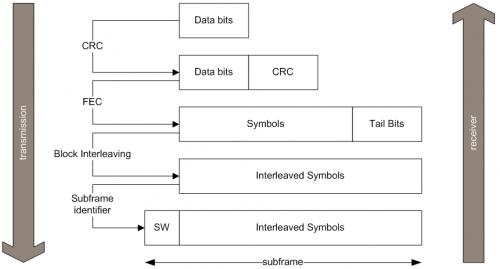
Figure 1 illustrates an example of how data is coded into the message structure, using the case of Galileo signals, where the subframe is the atomic element and frames are concatenations of subframes. Each step is further detailed in the following sections. | Figure 1 illustrates an example of how data is coded into the message structure, using the case of Galileo signals, where the subframe is the atomic element and frames are concatenations of subframes. Each step is further detailed in the following sections. | ||
[[File:ddp_sequence.png|center|thumb|500px|'''''Figure 1:''''' Example of a sequence of data (de)modulation using the Galileo example.]] | |||
==Synchronization== | |||
GNSS receivers perform two kinds of synchronization at Data Demodulation level: ''symbol'' synchronization (also called bit synchronization for signals that are not FEC encoded) and ''frame'' synchronization. | |||
==Synchronization== | ===Symbol Synchronization=== | ||
For the case of GPS L1 C/A, where the PRN code duration is 1 ms and 1 data bit lasts 20 ms, there are 20 pseudo-symbols in each symbol. In other words, if the receiver is correctly tracking the signal and the correlators are being integrated over a single PRN code (1 ms), the outputs will be sets of 20 identical pseudo-symbols, where each set corresponds to a symbol. | |||
A common way to achieve symbol synchronization is by means of histograms and counters<ref name="dierendonck">A. J. Van Dierendonck, “GPS Receivers”, from “Global Positioning System: Theory and Applications”, Volume I, Edited by B. W. Parkinson, J. J. Spilker Jr.</ref>. | |||
After symbol synchronization is achieved, GNSS receivers typically increase the correlators' integration times up to the symbol duration (e.g. 20 ms for GPS L1 C/A), and start outputting (integrated) symbols, while checking that the histogram does not slip. | |||
A | ===Frame Synchronization=== | ||
Frame synchronization consists in identifying the message subframes from the sequence of symbols. For the case of GPS L1 C/A, frame synchronization is achieved by looking for the preamble “10001011”, which flags the beginning of each subframe of the navigation message. These preambles are also called ''Synchronization Words'' (SW). | |||
With this in mind, it is clear that at this point: | |||
* | *the receiver is able to retrieve the navigation message bits, using the applicable SIS ICD, in case the message has no encoding (e.g. for GPS L1 C/A). | ||
*the receiver is able to retrieve the symbols for each subframe, although they still need to be decoded, in case the message is encoded (e.g. for Galileo Open Service). | |||
*the receiver is able to retrieve the symbols for each subframe, | |||
==Data Demodulation== | ==Data Demodulation== | ||
Data demodulation consists in extracting the bits of the navigation message with the maximum level of confidence. The steps required to achieve this goal actually depend on the signal at hand, and the applicable SIS ICD should be consulted on a case by case basis. Some of the techniques used are briefly described. | |||
===Parity Decoding=== | |||
The parity of pre-defined sets of bits (e.g. words) is checked against a field containing the parity computed at transmission and sent within the navigation message. Any discrepancies would imply that there was at least one error in the message. | |||
===Cyclic Redundancy Checks (CRC)=== | |||
Cyclic Redundancy Checks, commonly known as CRC<ref>[[Wikipedia:Cyclic redundancy check|Cyclic redundancy check in Wikipedia]]</ref> use pre-defined polynomials to compare check values computed locally (at the receiver) with the ones conveyed in the message and generated at transmission. | |||
===Forward Error Correction (FEC)=== | |||
FEC encoding<ref>[[Wikipedia:Forward error correction|Forward error correction in Wikipedia]]</ref> consists in representing bits with more than one symbol: this way, redundant information is transmitted, allowing the receiver to detect and correct some potential errors, hence improving the performance of the channel. As an example, Galileo Open Service use forward error convolutional codes with a constraint length of 7 and a coding rate of 1/2 to spread the navigation message, i.e. one bit is encoded with two symbols. Receivers may use Viterbi decoders<ref>[[Wikipedia:Viterbi decoder|Viterbi decoder in Wikipedia]]</ref> to recover the transmitted navigation message. | |||
===Block Interleaving=== | |||
Block Interleaving consists in transmitting the symbols in a different order. As an example, Galileo Open Service assembles the symbols in blocks of ''M'' columns by N ''rows'', and then transposes the block before sending the symbols in the SIS. The reverse operation needs to be conducted at the receiver end, in order to recover the original symbol sequence. The advantage of block interleaving is that it renders the message more robust to burst errors, since burst errors are now spread over a larger part of the message and may be still recoverable, e.g. using FEC decoding techniques which have some capabilities to correct errors. | |||
==Generation of Basic Observables== | |||
At this point, the receiver is tracking the incoming signal and has extracted the navigation message, and therefore can compute the observables. Although Doppler frequency is quite straight forward, and can be directly taken from the [[Frequency Lock Loop (FLL)|FLL]] or the instantaneous phase measured at the [[Phase Lock Loop (PLL)|PLL]], the pseudorange still needs to be computed from the code delay values provided by the [[Delay Lock Loop (DLL)|DLL]]. | |||
The pseudo-range to a given satellite ''m'' can be computed as: | |||
<math>\rho^m=c(T_U^m - T_S^m)\,</math> | |||
where: | |||
*<math>T_S\,</math> is the transmission time using the satellite clock, which has an error relative to an absolute time reference (e.g. GPS time). | |||
*<math>T_U\,</math> is the reception time using the receiver clock, which has an error relative to an absolute time reference (e.g. GPS time), plus all propagation delays, equipment delays and noise. | |||
*<math>c\,</math> is the speed of light. | |||
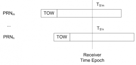
In reality, most GNSS receivers extrapolate the transmission time (at satellite clock) for all satellites at each receiver time epoch. Figure 2 illustrates this concept: <math>T_S’\,</math> are extrapolated for satellites ''m'' and ''n'', where ''TOW'' (Time Of Week) is the time stamp recorded by the satellite at the beginning of each subframe. | |||
[[File:ddp_extrapol.png|center|thumb|450px|'''''Figure 2:''''' Extrapolation of transmission time at each receiver time epoch.]] | [[File:ddp_extrapol.png|center|thumb|450px|'''''Figure 2:''''' Extrapolation of transmission time at each receiver time epoch.]] | ||
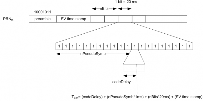
Figure 3 illustrates the computation of the extrapolated transmission time at the receiver, using the example of GPS L1 C/A, where 1 bit lasts 20 ms and considering that each pseudo-symbol lasts 1 ms (correlators are being integrated over one single PRN code). The code delay is the value output by the [[Delay Lock Loop (DLL)|DLL]]. | |||
Figure 3 | [[File:ddp_example.png|center|thumb|650px|'''''Figure 3:''''' Example of computation of extrapolated transmitted time.]] | ||
==Applications Processing== | |||
Finally, this information is passed to the Applications Processing block, which: | |||
[[ | *[[GNSS Basic Observables|Processes the GNSS observables]]. | ||
*[[Solving navigation equations|Computes the navigation solution]]. | |||
*[[GNSS Applications|Implements the user applications]]. | *[[GNSS Applications|Implements the user applications]]. | ||
| Line 102: | Line 98: | ||
*[[Generic Receiver Description]] | *[[Generic Receiver Description]] | ||
*[[Digital Signal Processing]] | *[[Digital Signal Processing]] | ||
*[[GNSS | *[[Combination of GNSS Measurements]] | ||
*[[GNSS Basic Observables]] | |||
*[[Solving navigation equations]] | *[[Solving navigation equations]] | ||
*[[GNSS Applications]] | *[[GNSS Applications]] | ||
| Line 108: | Line 105: | ||
==References== | ==References== | ||
<references/> | <references/> | ||
[[Category:Receivers]] | [[Category:Receivers]] | ||
Latest revision as of 16:36, 18 September 2014
| Receivers | |
|---|---|
| Title | Data Demodulation and Processing |
| Edited by | GMV |
| Level | Advanced |
| Year of Publication | 2011 |
While the tracking loops extract code and carrier information to synchronize the locally generated PRN code with the incoming signal, the Data demodulation and Processing block aims at extracting “useful information” to be used by the applications processing block, when generating a navigation solution. The core of this information consists on the navigation message and the observables, namely pseudorange and Doppler frequency.
Concept
The inputs to the Data Demodulation and Processing block are the measurements from the tracking loops (code and carrier information), as well as the sign of the Prompt correlator outputs. In fact, when a signal is being correctly tracked, the sign of the Prompt correlator output is positive when the transmitted navigation symbol is 1 and negative when the symbol is -1, by definition of correlation.
The following nomenclature is used herein:
- Pseudo-symbol: binary information corresponding to an excerpt of a symbol over an integration time interval (i.e. sign of the prompt correlator output, integrated over at least one PRN code period).
- Symbol: binary information corresponding to the encoded navigation message (e.g. for GPS L1 C/A, symbols are the same as bits, but for Galileo signals, each data bit is encoded with two symbols using FEC).
- Data Bit: binary information corresponding to the navigation message.
The process to extract the information necessary to compute a navigation solution consists in:
- Synchronization, both at bit / symbol and frame level.
- Data demodulation, to extract data bits of the navigation message.
- Generation of GNSS observables.
- Applications processing, like PVT computation.
Figure 1 illustrates an example of how data is coded into the message structure, using the case of Galileo signals, where the subframe is the atomic element and frames are concatenations of subframes. Each step is further detailed in the following sections.
Synchronization
GNSS receivers perform two kinds of synchronization at Data Demodulation level: symbol synchronization (also called bit synchronization for signals that are not FEC encoded) and frame synchronization.
Symbol Synchronization
For the case of GPS L1 C/A, where the PRN code duration is 1 ms and 1 data bit lasts 20 ms, there are 20 pseudo-symbols in each symbol. In other words, if the receiver is correctly tracking the signal and the correlators are being integrated over a single PRN code (1 ms), the outputs will be sets of 20 identical pseudo-symbols, where each set corresponds to a symbol.
A common way to achieve symbol synchronization is by means of histograms and counters[1].
After symbol synchronization is achieved, GNSS receivers typically increase the correlators' integration times up to the symbol duration (e.g. 20 ms for GPS L1 C/A), and start outputting (integrated) symbols, while checking that the histogram does not slip.
Frame Synchronization
Frame synchronization consists in identifying the message subframes from the sequence of symbols. For the case of GPS L1 C/A, frame synchronization is achieved by looking for the preamble “10001011”, which flags the beginning of each subframe of the navigation message. These preambles are also called Synchronization Words (SW).
With this in mind, it is clear that at this point:
- the receiver is able to retrieve the navigation message bits, using the applicable SIS ICD, in case the message has no encoding (e.g. for GPS L1 C/A).
- the receiver is able to retrieve the symbols for each subframe, although they still need to be decoded, in case the message is encoded (e.g. for Galileo Open Service).
Data Demodulation
Data demodulation consists in extracting the bits of the navigation message with the maximum level of confidence. The steps required to achieve this goal actually depend on the signal at hand, and the applicable SIS ICD should be consulted on a case by case basis. Some of the techniques used are briefly described.
Parity Decoding
The parity of pre-defined sets of bits (e.g. words) is checked against a field containing the parity computed at transmission and sent within the navigation message. Any discrepancies would imply that there was at least one error in the message.
Cyclic Redundancy Checks (CRC)
Cyclic Redundancy Checks, commonly known as CRC[2] use pre-defined polynomials to compare check values computed locally (at the receiver) with the ones conveyed in the message and generated at transmission.
Forward Error Correction (FEC)
FEC encoding[3] consists in representing bits with more than one symbol: this way, redundant information is transmitted, allowing the receiver to detect and correct some potential errors, hence improving the performance of the channel. As an example, Galileo Open Service use forward error convolutional codes with a constraint length of 7 and a coding rate of 1/2 to spread the navigation message, i.e. one bit is encoded with two symbols. Receivers may use Viterbi decoders[4] to recover the transmitted navigation message.
Block Interleaving
Block Interleaving consists in transmitting the symbols in a different order. As an example, Galileo Open Service assembles the symbols in blocks of M columns by N rows, and then transposes the block before sending the symbols in the SIS. The reverse operation needs to be conducted at the receiver end, in order to recover the original symbol sequence. The advantage of block interleaving is that it renders the message more robust to burst errors, since burst errors are now spread over a larger part of the message and may be still recoverable, e.g. using FEC decoding techniques which have some capabilities to correct errors.
Generation of Basic Observables
At this point, the receiver is tracking the incoming signal and has extracted the navigation message, and therefore can compute the observables. Although Doppler frequency is quite straight forward, and can be directly taken from the FLL or the instantaneous phase measured at the PLL, the pseudorange still needs to be computed from the code delay values provided by the DLL.
The pseudo-range to a given satellite m can be computed as:
[math]\displaystyle{ \rho^m=c(T_U^m - T_S^m)\, }[/math]
where:
- [math]\displaystyle{ T_S\, }[/math] is the transmission time using the satellite clock, which has an error relative to an absolute time reference (e.g. GPS time).
- [math]\displaystyle{ T_U\, }[/math] is the reception time using the receiver clock, which has an error relative to an absolute time reference (e.g. GPS time), plus all propagation delays, equipment delays and noise.
- [math]\displaystyle{ c\, }[/math] is the speed of light.
In reality, most GNSS receivers extrapolate the transmission time (at satellite clock) for all satellites at each receiver time epoch. Figure 2 illustrates this concept: [math]\displaystyle{ T_S’\, }[/math] are extrapolated for satellites m and n, where TOW (Time Of Week) is the time stamp recorded by the satellite at the beginning of each subframe.
Figure 3 illustrates the computation of the extrapolated transmission time at the receiver, using the example of GPS L1 C/A, where 1 bit lasts 20 ms and considering that each pseudo-symbol lasts 1 ms (correlators are being integrated over one single PRN code). The code delay is the value output by the DLL.
Applications Processing
Finally, this information is passed to the Applications Processing block, which:
Related articles
- Generic Receiver Description
- Digital Signal Processing
- Combination of GNSS Measurements
- GNSS Basic Observables
- Solving navigation equations
- GNSS Applications
References
- ^ A. J. Van Dierendonck, “GPS Receivers”, from “Global Positioning System: Theory and Applications”, Volume I, Edited by B. W. Parkinson, J. J. Spilker Jr.
- ^ Cyclic redundancy check in Wikipedia
- ^ Forward error correction in Wikipedia
- ^ Viterbi decoder in Wikipedia


