If you wish to contribute or participate in the discussions about articles you are invited to contact the Editor
GPS Signal Plan: Difference between revisions
Gema.Cueto (talk | contribs) No edit summary |
Gema.Cueto (talk | contribs) |
||
| (One intermediate revision by the same user not shown) | |||
| Line 14: | Line 14: | ||
* The P Code is the precision signal and is coded by the precision code. Moreover the Y-Code is used in place of the P-code whenever the Anti-Spoofing (A/S) mode of operation is activated as described in the ICDs 203, 224 and 225. The PRN P-code for SV number i is a ranging code, Pi(t), 7 days long at a chipping rate of 10.23 Mbps. The 7 day sequence is the Modulo-2 sum of two sub-sequences referred to as <math>X_1</math> and <math>X_{2i}</math> with 15,345,000 chips and 15,345,037 chips, respectively. The <math>X_{2i}</math> sequence is an <math>X_2</math> sequence selectively delayed by 1 to 37 chips allowing the basic code generation technique to produce a set of 37 mutually exclusive P-code sequences 7 days long. | * The P Code is the precision signal and is coded by the precision code. Moreover the Y-Code is used in place of the P-code whenever the Anti-Spoofing (A/S) mode of operation is activated as described in the ICDs 203, 224 and 225. The PRN P-code for SV number i is a ranging code, Pi(t), 7 days long at a chipping rate of 10.23 Mbps. The 7 day sequence is the Modulo-2 sum of two sub-sequences referred to as <math>X_1</math> and <math>X_{2i}</math> with 15,345,000 chips and 15,345,037 chips, respectively. The <math>X_{2i}</math> sequence is an <math>X_2</math> sequence selectively delayed by 1 to 37 chips allowing the basic code generation technique to produce a set of 37 mutually exclusive P-code sequences 7 days long. | ||
* The modernized military signal (M-Code) is designed exclusively for military use and is intended to eventually replace the P(Y) code [E. D. Kaplan and C. Hegarty, 2006]<ref>[E. D. Kaplan and C. Hegarty, 2006] E. D. Kaplan and C. Hegarty, Understanding GPS: Principles and Applications-2nd Edition, Chapter 4.</ref>. The M-Code provides better jamming resistance than the P(Y) signal, primarily through enabling transmission at much higher power without interference with C/A code or P(Y) code receivers [B.C. Barker et al., 2000]<ref>[B.C. Barker et al., 2000] B.C. Barker, J.W. Betz, J.E. Clark, J.T. Correia, J.T. Gillis, S. Lazar, Lt. K. A. Rehborn, J.R. Straton, III, ARINC, Overview of the GPS M-Code Signal, Proceedings of the National Technical Meeting of the Institute of Navigation, ION-NTM 2000, 26-28 January 2000, Anaheim, California, USA.</ref>. Moreover, the M-Code provides more robust signal acquisition than is achieved today, while offering better security in terms of exclusivity, authentication, and confidentiality, along with streamlined key distribution. In other aspects, the M-Code signal provides much better performance than the P(Y) Code and more flexibility. | * The modernized military signal (M-Code) is designed exclusively for military use and is intended to eventually replace the P(Y) code [E. D. Kaplan and C. Hegarty, 2006]<ref>[E. D. Kaplan and C. Hegarty, 2006] E. D. Kaplan and C. Hegarty, Understanding GPS: Principles and Applications-2nd Edition, Chapter 4.</ref>. The M-Code provides better jamming resistance than the P(Y) signal, primarily through enabling transmission at much higher power without interference with C/A code or P(Y) code receivers [B.C. Barker et al., 2000]<ref>[B.C. Barker et al., 2000] B.C. Barker, J.W. Betz, J.E. Clark, J.T. Correia, J.T. Gillis, S. Lazar, Lt. K. A. Rehborn, J.R. Straton, III, ARINC, Overview of the GPS M-Code Signal, Proceedings of the National Technical Meeting of the Institute of Navigation, ION-NTM 2000, 26-28 January 2000, Anaheim, California, USA.</ref>. Moreover, the M-Code provides more robust signal acquisition than is achieved today, while offering better security in terms of exclusivity, [[GNSS Authentication and encryption | authentication]], and confidentiality, along with streamlined key distribution. In other aspects, the M-Code signal provides much better performance than the P(Y) Code and more flexibility. | ||
* The new L1 Civil signal (L1C), defined in the [GPS ICD-800]<ref name="GPS_SIS_ICD_800">[GPS ICD-800] Revision G, "Navstar GPS Space Segment/User Segment L1C Interfaces".</ref>, has been designed for interoperability with Galileo E1. It is compatible with current L1 signal but broadcast at a higher power level and includes advanced design for enhanced performance. It consists of two main components; one denoted <math>L1C_P</math> to represent the pilot signal, consisting of a time-multiplexing of BOC(1,1) and BOC(6,1), thus without any data message, and <math>L1C_D</math>, with a pure BOC(1,1), for the data channel. This is spread by a ranging code and modulated by a data message. The pilot channel <math>L1C_P</math> is also modulated by an SV unique overlay secondary code, <math>L1C_O</math>. An enhancement to this L1C signal is being analysed, which is called CHIMERA (Chips Message Robust Authentication). This technique consists on adding encrypted watermarks to the L1C signal that not only let users know when a signal is being spoofed but also makes it possible to authenticate the location of a GPS receiver to another party. | * The new L1 Civil signal (L1C), defined in the [GPS ICD-800]<ref name="GPS_SIS_ICD_800">[GPS ICD-800] Revision G, "Navstar GPS Space Segment/User Segment L1C Interfaces".</ref>, has been designed for interoperability with Galileo E1. It is compatible with current L1 signal but broadcast at a higher power level and includes advanced design for enhanced performance. It consists of two main components; one denoted <math>L1C_P</math> to represent the pilot signal, consisting of a time-multiplexing of BOC(1,1) and BOC(6,1), thus without any data message, and <math>L1C_D</math>, with a pure BOC(1,1), for the data channel. This is spread by a ranging code and modulated by a data message. The pilot channel <math>L1C_P</math> is also modulated by an SV unique overlay secondary code, <math>L1C_O</math>. An enhancement to this L1C signal is being analysed, which is called CHIMERA (Chips Message Robust Authentication). This technique consists on adding encrypted watermarks to the L1C signal that not only let users know when a signal is being spoofed but also makes it possible to [[GNSS Authentication and encryption | authenticate]] the location of a GPS receiver to another party. | ||
Latest revision as of 12:05, 29 January 2021
| GPS | |
|---|---|
| Title | GPS Signal Plan |
| Author(s) | J.A Ávila Rodríguez, University FAF Munich, Germany. |
| Level | Advanced |
| Year of Publication | 2011 |
GPS L1 Band
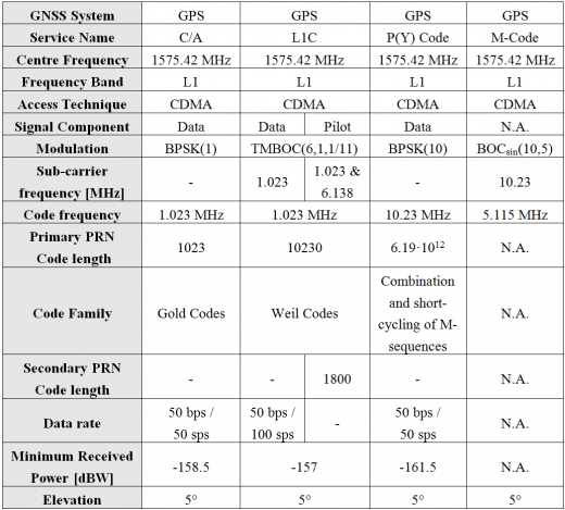
The GPS L1 band (1575.42 MHz) has turned to be the most important band for navigation purposes. Indeed most of the applications in the world nowadays are based on the signals transmitted at this frequency. Three signals are transmitted at the moment by GPS in L1: C/A Code, P(Y) Code,M-Code and the new L1C signal, which is in the process of being fielded as L2C and L5. The legacy civil signal, called L1 C/A or C/A at L1, will continue broadcasting in the future. We describe all of these signals modulated in the L1 RF carrier frequency in the next lines:
- The Coarse/Acquisition (C/A) code signal was primarily thought for acquisition of the P (or Y) code and has become nowadays the most important signal for mass market applications. The PRN C/A Code for SV ID number i is a Gold code, [math]\displaystyle{ G_i (t) }[/math], of 1 millisecond in length at a chipping rate of 1.023 Mbps. The [math]\displaystyle{ G_i (t) }[/math] sequence is a linear pattern generated by the Modulo-2 addition of two subsequences, [math]\displaystyle{ G_1 }[/math] and [math]\displaystyle{ G_{1i} }[/math], each of them being a 1023 chip long linear pattern. The epochs of the Gold code are synchronized with the [math]\displaystyle{ X_1 }[/math] epochs of the P-code.
- The P Code is the precision signal and is coded by the precision code. Moreover the Y-Code is used in place of the P-code whenever the Anti-Spoofing (A/S) mode of operation is activated as described in the ICDs 203, 224 and 225. The PRN P-code for SV number i is a ranging code, Pi(t), 7 days long at a chipping rate of 10.23 Mbps. The 7 day sequence is the Modulo-2 sum of two sub-sequences referred to as [math]\displaystyle{ X_1 }[/math] and [math]\displaystyle{ X_{2i} }[/math] with 15,345,000 chips and 15,345,037 chips, respectively. The [math]\displaystyle{ X_{2i} }[/math] sequence is an [math]\displaystyle{ X_2 }[/math] sequence selectively delayed by 1 to 37 chips allowing the basic code generation technique to produce a set of 37 mutually exclusive P-code sequences 7 days long.
- The modernized military signal (M-Code) is designed exclusively for military use and is intended to eventually replace the P(Y) code [E. D. Kaplan and C. Hegarty, 2006][1]. The M-Code provides better jamming resistance than the P(Y) signal, primarily through enabling transmission at much higher power without interference with C/A code or P(Y) code receivers [B.C. Barker et al., 2000][2]. Moreover, the M-Code provides more robust signal acquisition than is achieved today, while offering better security in terms of exclusivity, authentication, and confidentiality, along with streamlined key distribution. In other aspects, the M-Code signal provides much better performance than the P(Y) Code and more flexibility.
- The new L1 Civil signal (L1C), defined in the [GPS ICD-800][3], has been designed for interoperability with Galileo E1. It is compatible with current L1 signal but broadcast at a higher power level and includes advanced design for enhanced performance. It consists of two main components; one denoted [math]\displaystyle{ L1C_P }[/math] to represent the pilot signal, consisting of a time-multiplexing of BOC(1,1) and BOC(6,1), thus without any data message, and [math]\displaystyle{ L1C_D }[/math], with a pure BOC(1,1), for the data channel. This is spread by a ranging code and modulated by a data message. The pilot channel [math]\displaystyle{ L1C_P }[/math] is also modulated by an SV unique overlay secondary code, [math]\displaystyle{ L1C_O }[/math]. An enhancement to this L1C signal is being analysed, which is called CHIMERA (Chips Message Robust Authentication). This technique consists on adding encrypted watermarks to the L1C signal that not only let users know when a signal is being spoofed but also makes it possible to authenticate the location of a GPS receiver to another party.
For more details on the code generation refer to the [GPS ICD 200][4] and [GPS ICD-800][3]. Finally, the technical characteristics of the existing GPS signals in the L1 band are summarized in the following Table 1.
Of all the signals above, the C/A Code is the best known as most of the receivers that have been built until today are based on it. The C/A Code was open from the very beginning to all users, although until May 1st, 2000 an artificial degradation was introduced by means of the Select Availability (SA) mechanism which added an intentional distortion to degrade the positioning quality of the signal to non-desired users. As we have already mentioned, the C/A Code was thought to be an aid for the P(Y) Code (to realize a Coarse Acquisition). The M-Code is the last military signal that has been introduced in GPS.
For a long time different signal structures for the M-Code were under consideration [J.W. Betz, 2001] [5]being the Manchester code signals (BPSK) and the binary offset carrier (BOC) signals the two favored candidates. Both solutions result from the modulation of a non-return to zero (NRZ) pseudo random noise spreading code by a square-wave sub-carrier. While the Manchester code has a spreading code of rate equal to that of the square-wave, the BOC signal does not necessarily have to be so, being the only constraint that the rate of the spreading code must be less than the sub-carrier frequency.
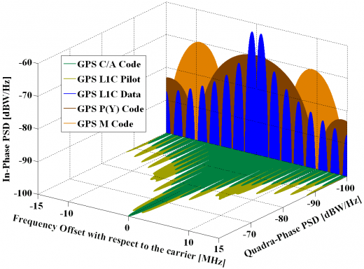
The interesting aspect about these signals is that, like the conventional sub-carrier modulation, the waveform presents a zero at the carrier frequency due to the square-wave sub-carrier. In fact, their split-power spectra clearly facilitate the compatibility of the GPS military M-Code signal with the existing C/A Code and P(Y) Code.
We can clearly recognize that GPS L1C concentrates more power at higher frequencies – due to BOC(6,1) – in the pilot channel than in the data channel (please refer to Time-Multiplexed BOC (TMBOC) for further details).
Finally, it is important to note that for all the figures next the commonly used expressions for bandwidths in MHz must be understood as multiplied by the factor 1.023. Thus BPSK(10) refers in reality to a BPSK signal with a chip rate of 10.23 MHz. This remains valid for all the bandwidths in this thesis, unless different stated.
GPS L2 Band
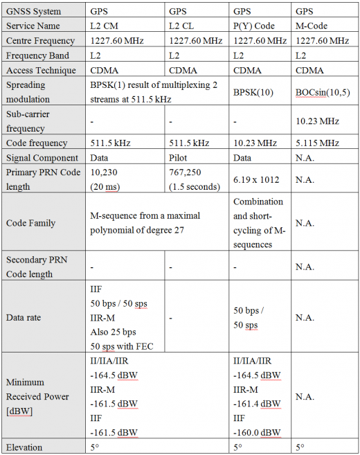
GPS is transmitting in the L2 band (1227.60 MHz) a modernized civil signal known as L2C designed specifically to meet commercial needs as it enables the development of dual-frequency solutions; together with the P(Y) Code and the M-Code. The P(Y) Code and M-Code were already described shortly in the previous chapter and the properties and parameters are thus similar to those in the L1 band. In addition, for Block IIR-M, IIF, and subsequent blocks of SVs, two additional PRN ranging codes are transmitted. They are the L2 Civil Moderate (L2 CM) code and the L2 Civil Long (L2 CL) code. These two signals are time multiplexed so that the resulting chipping rate is double as high as that of each individual signal. We further describe them in the next lines more in detail:
- L2 CM Code is transmitted in the IIR-M, IIF, III and subsequent blocks. The PRN L2 CM Code for SV number i is a ranging code, [math]\displaystyle{ CM_i(t) }[/math], which is 20 milliseconds in length at a chipping rate of 511.5 Kbps. The epochs of the L2 CM Code are synchronized with the X1 epochs of the P-code. The [math]\displaystyle{ CM_i(t) }[/math] sequence is a linear pattern which is short cycled every count period of 10,230 chips by resetting with a particular initial state. Furthermore, for Block IIR-M, the navigation data is also Modulo-2 added to the L2 CM Code. It is interesting to note that the navigation data can be used in one of two different data rates selectable by ground command:
- D(t) with a data rate of 50 bps
- D(t) with a symbol rate of 50 symbols per second (sps) which is obtained by encoding D(t) with a data rate of 25 bps coded in a rate 1/2 convolutional code. Finally, the resultant bit-train is combined with the L2 CL Code using time-division multiplexing.
- L2 CL Code is transmitted in the IIR-M, IIF, III and subsequent blocks. The PRN L2 CL Code for SV number is a ranging code, [math]\displaystyle{ CL_i(t) }[/math], which is 1.5 seconds in length at a chipping rate of 511.5 Kbps. The epochs of the L2 CL Code are synchronized with the X1 epochs of the P Code. The [math]\displaystyle{ CL_i(t) }[/math] sequence is a linear pattern which is generated using the same code generator polynomial as of [math]\displaystyle{ CM_i(t) }[/math]. However, the [math]\displaystyle{ CL_i(t) }[/math] sequence is short cycled by resetting with an initial state every count period of 767,250 chips.
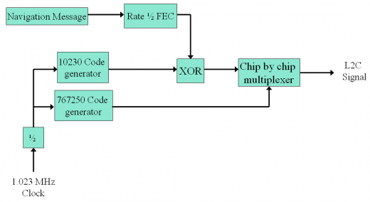
Finally, it is important to note that the GPS L2 band will have a transition period from the C/A Code to L2C and mixed configurations could occur. Next figure shows the baseband L2 signal generation scheme. As we can recognize, although the chipping rate of the L2 CM and L2 CL signals is of 511.5 Kbps individually, after the time multiplexing the composite signal results in a stream of 1.023 MHz.
The technical characteristics of the GPS L2 signals are summarized next:
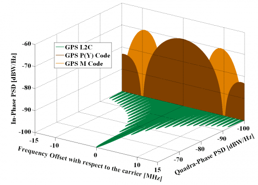
The spectra of the different signals described in the preceding lines are shown in the next Figure 3:
GPS L5 Band
The GPS L5 (1176.45 MHz) signal is one of the new signals belonging to the GPS modernization plan. It is broadcast in a radio band reserved exclusively for aviation safety services and the signal is thought to be used in combination with L1 C/A to improve accuracy (via ionospheric correction) and robustness (via signal redundancy). It is transmitted at a higher power level than current civil GPS signals, has a wider bandwidth and has lower frequency which enhances reception for indoor users.
The L5 signal consists of two carrier components that are in phase quadrature with each other. Each carrier component is bi-phase shift key (BPSK) modulated by a separate bit train. One bit train is module-2 sum of the I5-code, NAV data, and synchronization sequence while the other is the Q5-code with no NAV data, but with another synchronization sequence. For a particular SV, all transmitted signal elements (carriers, codes, synchronization sequence and data) are coherently and derived from the same on-board frequency source.
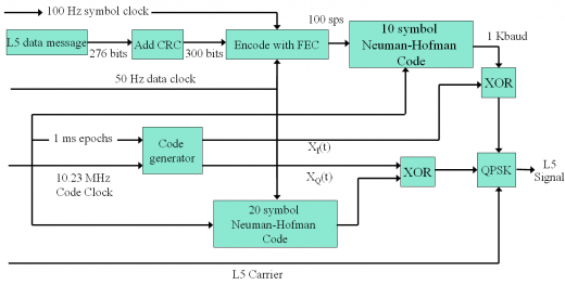
The L5 data channel and the L5 pilot channel are the two carrier frequencies. Moreover, two PRN ranging codes are transmitted on L5. The PRN L5-codes for SV number i are independent, but time synchronized ranging codes ,[math]\displaystyle{ X_I^i(t) }[/math] and [math]\displaystyle{ X_Q^i(t) }[/math], of 1 millisecond in length at a chipping rate of 10.23 Mbps [GPS ICD-705][6]. For each code, the 1-millisecond sequences are the modulo-2 sum of two sub-sequences referred to as XA and XBi with lengths of 8,190 chips and 8,191 chips respectively, which restart to generate the 10,230 chip code. The XBi sequence is selectively delayed, thereby allowing the basic code generation technique to produce the different satellite codes.
The generation scheme can be shown graphically as follows:
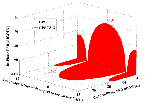
For more details on L5, refer to [E. D. Kaplan and C. Hegarty, 2006]. The different signals present the following spectrum:
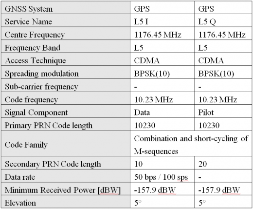
To conclude, the technical characteristics of the GPS signals in L5 can be summarized as follows:
GPS Modernization
Before December 2005 the basic GPS capability consisted of the Standard Positioning Service (SPS) provided by the C/A Code on the L1 frequency and the Precise Positioning Service (PPS) provided by the P(Y) Code on L1 and L2. Although those services are of relatively good quality, the United States proposed a modernization plan in order to improve the quality and protection of both civil and military users which includes, among other features, the provision of additional signals (e.g. L5, L1C). These signals are being gradually deployed in the GPS system while the constellation is being renewed.
References
- ^ [E. D. Kaplan and C. Hegarty, 2006] E. D. Kaplan and C. Hegarty, Understanding GPS: Principles and Applications-2nd Edition, Chapter 4.
- ^ [B.C. Barker et al., 2000] B.C. Barker, J.W. Betz, J.E. Clark, J.T. Correia, J.T. Gillis, S. Lazar, Lt. K. A. Rehborn, J.R. Straton, III, ARINC, Overview of the GPS M-Code Signal, Proceedings of the National Technical Meeting of the Institute of Navigation, ION-NTM 2000, 26-28 January 2000, Anaheim, California, USA.
- ^ a b [GPS ICD-800] Revision G, "Navstar GPS Space Segment/User Segment L1C Interfaces".
- ^ [GPS ICD-200] Revision L, "Navstar GPS Space Segment/User Segment Interfaces".
- ^ [J.W. Betz, 2001a] J.W. Betz, Binary Offset Carrier Modulations for Radionavigation, NAVIGATION: Journal of The Institute of Navigation Vol. 48, No. 4, Winter 2001/02
- ^ [GPS ICD-705] Revision G, "Navstar GPS Space Segment/User Segment L5 Interfaces"
Credits
The information presented in this NAVIPEDIA’s article is an extract of the PhD work performed by Dr. Jose Ángel Ávila Rodríguez in the FAF University of Munich as part of his Doctoral Thesis “On Generalized Signal Waveforms for Satellite Navigation” presented in June 2008, Munich (Germany)
The information of this article is regularly updated in line with the GPS modernization plan updates. Applicable GPS ICD documents can be found in https://www.gps.gov/technical/icwg/

