If you wish to contribute or participate in the discussions about articles you are invited to contact the Editor
Pole Tide: Difference between revisions
Jaume.Sanz (talk | contribs) No edit summary |
Jaume.Sanz (talk | contribs) No edit summary |
||
| (2 intermediate revisions by the same user not shown) | |||
| Line 8: | Line 8: | ||
The instantaneous earth rotation axis shifts inside a square of about <math>20</math> meters in relation to a point with fixed coordinates on the earth (i.e., Chandler wobble with a period of <math>14</math> months). This entails a varying elastic response of the earth's crust. This has an effect smaller than <math>2.5</math> centimetres in vertical and <math>0.7</math> centimetres in horizontal, but must be taken into account if the observations are carried out over periods longer than two months. | The instantaneous earth rotation axis shifts inside a square of about <math>20</math> meters in relation to a point with fixed coordinates on the earth (i.e., Chandler wobble with a period of <math>14</math> months). This entails a varying elastic response of the earth's crust. This has an effect smaller than <math>2.5</math> centimetres in vertical and <math>0.7</math> centimetres in horizontal, but must be taken into account if the observations are carried out over periods longer than two months. | ||
From the IERS Conventions [Denis et al., 2004] <ref> [Denis et al., 2004] Denis, D., McCarthy and Petit, G., 2004. IERS Conventions (2003). IERS Technical Note 32.. IERS Convention Center., Frankfurt am Main.</ref>, pages 83-84, the following expression <ref group="footnotes"> Notice the use of latitude <math>\displaystyle \varphi</math> in equations (1 and 2), instead of the co-latitude <math>\displaystyle \theta</math> used in the IERS equations.</ref> can be derived for the displacement at a point of | From the IERS Conventions [Denis et al., 2004] <ref> [Denis et al., 2004] Denis, D., McCarthy and Petit, G., 2004. IERS Conventions (2003). IERS Technical Note 32.. IERS Convention Center., Frankfurt am Main.</ref>, pages 83-84, the following expression <ref group="footnotes"> Notice the use of latitude <math>\displaystyle \varphi</math> in equations (1 and 2), instead of the co-latitude <math>\displaystyle \theta</math> used in the IERS equations.</ref> can be derived for the displacement at a point of geocentric latitude <math>\displaystyle \varphi</math> and longitude <math>\displaystyle \lambda</math>: | ||
| Line 22: | Line 22: | ||
Taking the earth's angular rotation <math>\omega_E= 7.29\cdot 10^{-5}</math>, the earth's equatorial radius <math>R_e=6378\, | Taking the earth's angular rotation <math>\omega_E= 7.29\cdot 10^{-5} rad/s</math>, the earth's equatorial radius <math>R_e=6378\cdot 10^3\, m</math> and the gravitational acceleration <math>g=9.8\, m/sec^2</math>, it follows: | ||
| Line 36: | Line 36: | ||
The displacement <math>\displaystyle \delta</math> is given in the radial, longitude and latitude <math>(\hat{\mathbf r}, \hat{\boldsymbol \lambda}, \hat{\boldsymbol \varphi})</math> vectors, | The displacement <math>\displaystyle \delta</math> is given in the radial, longitude and latitude <math>(\hat{\mathbf r}, \hat{\boldsymbol \lambda}, \hat{\boldsymbol \varphi})</math> vectors (positive upwards, eastwards and northwards, respectively). | ||
Thus, the displacement vector in the (x, y, z) ECEF Cartesian coordinates is given by | |||
::<math> | ::<math> | ||
| Line 66: | Line 66: | ||
::[[File:Pole_Tide_UEN2CTS.png|none|thumb|400px|'''''Figure 1:''''' Transformation from UEN <math>(\hat{\mathbf r}, \hat{\boldsymbol \lambda}, \hat{\boldsymbol \varphi})</math> to TRS <math>(x,y,x)</math> coordinates.]] | ::[[File:Pole_Tide_UEN2CTS.png|none|thumb|400px|'''''Figure 1:''''' Transformation from UEN <math>(\hat{\mathbf r}, \hat{\boldsymbol \lambda}, \hat{\boldsymbol \varphi})</math> to TRS <math>(x,y,x)</math> coordinates.]] | ||
where <math> {{\mathbf R}_3(-\lambda )\cdot {\mathbf R}_2(\varphi )} </math> are the rotations in latitude (1) and longitude (2) indicated in figure 1 (see [[Reference Frames in GNSS]]). | |||
Latest revision as of 07:33, 5 April 2013
| Fundamentals | |
|---|---|
| Title | Pole Tide |
| Author(s) | J. Sanz Subirana, J.M. Juan Zornoza and M. Hernández-Pajares, Technical University of Catalonia, Spain. |
| Level | Intermediate |
| Year of Publication | 2011 |

The instantaneous earth rotation axis shifts inside a square of about [math]\displaystyle{ 20 }[/math] meters in relation to a point with fixed coordinates on the earth (i.e., Chandler wobble with a period of [math]\displaystyle{ 14 }[/math] months). This entails a varying elastic response of the earth's crust. This has an effect smaller than [math]\displaystyle{ 2.5 }[/math] centimetres in vertical and [math]\displaystyle{ 0.7 }[/math] centimetres in horizontal, but must be taken into account if the observations are carried out over periods longer than two months.
From the IERS Conventions [Denis et al., 2004] [1], pages 83-84, the following expression [footnotes 1] can be derived for the displacement at a point of geocentric latitude [math]\displaystyle{ \displaystyle \varphi }[/math] and longitude [math]\displaystyle{ \displaystyle \lambda }[/math]:
- [math]\displaystyle{ \begin{array}{ll} \delta_{\hat{\mathbf r}}=&-\frac{\omega^2_E \, R_e}{2\,g}\,h \, \sin 2\varphi \left ( m_1 \cos \lambda + m_2 \sin \lambda \right ) \,\hat {\mathbf r}\qquad \\[0.3cm] \delta_{\hat{\mathbf \lambda}}= & -\frac{\omega^2_E \, R_e}{g}\, l \, \sin \varphi \left (-m_1 \sin \lambda + m_2 \cos \lambda \right ) \, \hat{\mathbf \lambda} \qquad \\[0.3cm] \delta_{\hat{\mathbf \varphi}}= & -\frac{\omega^2_E \, R_e}{g}\, l\, \cos 2\varphi \left (\, m_1 \cos \lambda + m_2 \sin \lambda \right )\, \hat{\mathbf \varphi}\qquad \end{array} \qquad\mbox{(1)} }[/math]
where ([math]\displaystyle{ \displaystyle m_1 }[/math],[math]\displaystyle{ \displaystyle m_2 }[/math]) are the displacements (in meters) from the 1903.0 CIO, pole position, and [math]\displaystyle{ \displaystyle h= 0.6027 }[/math], [math]\displaystyle{ \displaystyle l=0.0836 }[/math] are the Love numbers.
Taking the earth's angular rotation [math]\displaystyle{ \omega_E= 7.29\cdot 10^{-5} rad/s }[/math], the earth's equatorial radius [math]\displaystyle{ R_e=6378\cdot 10^3\, m }[/math] and the gravitational acceleration [math]\displaystyle{ g=9.8\, m/sec^2 }[/math], it follows:
- [math]\displaystyle{ \begin{array}{ll} \delta_{\hat{\mathbf r}}=&-32 \, \sin 2\varphi \left ( x_1 \cos \lambda + x_2 \sin \lambda \right ) \, \hat {\mathbf r}\qquad \mbox{(mm)} \\[0.3cm] \delta_{\hat{\mathbf \lambda}}= & -9 \, \sin \varphi \left (-x_1 \sin \lambda + x_2 \cos \lambda \right ) \, \hat{\mathbf \lambda} \qquad \mbox{(mm)} \\[0.3cm] \delta_{\hat{\mathbf \varphi}}= & -9 \, \cos 2\varphi \left (\, x_1 \cos \lambda + x_2 \sin \lambda \right )\, \hat{\mathbf \varphi}\qquad \mbox{(mm)} \end{array} \qquad\mbox{(2)} }[/math]
where ([math]\displaystyle{ \displaystyle x_1 }[/math],[math]\displaystyle{ \displaystyle x_2 }[/math]) are the displacements (given in seconds of arc). Pole displacements can be found at ftp://hpiers.obspm.fr/iers/eop/eop.others.
The displacement [math]\displaystyle{ \displaystyle \delta }[/math] is given in the radial, longitude and latitude [math]\displaystyle{ (\hat{\mathbf r}, \hat{\boldsymbol \lambda}, \hat{\boldsymbol \varphi}) }[/math] vectors (positive upwards, eastwards and northwards, respectively).
Thus, the displacement vector in the (x, y, z) ECEF Cartesian coordinates is given by
- [math]\displaystyle{ \left[ \begin{array}{c} \Delta x \\ \Delta y \\ \Delta z \end{array} \right]= \underbrace{\left( \begin{array}{ccc} \cos \lambda \cos \varphi & -\sin \lambda & -\cos \lambda \sin \varphi \\ \sin \lambda \cos \varphi & \cos \lambda & -\sin \lambda \sin \varphi \\ \sin \varphi & 0 & \cos \Phi \end{array} \right)}_{{\mathbf R}_3(-\lambda )\cdot {\mathbf R}_2(\varphi )} \left[ \begin{array}{l} \delta_{\hat{\mathbf r}}\\ \delta_{\hat{\mathbf \lambda}}\\ \delta_{\hat{\mathbf \varphi}} \end{array} \right] \qquad\mbox{(2)} }[/math]
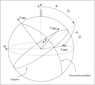
Figure 1: Transformation from UEN [math]\displaystyle{ (\hat{\mathbf r}, \hat{\boldsymbol \lambda}, \hat{\boldsymbol \varphi}) }[/math] to TRS [math]\displaystyle{ (x,y,x) }[/math] coordinates.

where [math]\displaystyle{ {{\mathbf R}_3(-\lambda )\cdot {\mathbf R}_2(\varphi )} }[/math] are the rotations in latitude (1) and longitude (2) indicated in figure 1 (see Reference Frames in GNSS).
Notes
- ^ Notice the use of latitude [math]\displaystyle{ \displaystyle \varphi }[/math] in equations (1 and 2), instead of the co-latitude [math]\displaystyle{ \displaystyle \theta }[/math] used in the IERS equations.
References
- ^ [Denis et al., 2004] Denis, D., McCarthy and Petit, G., 2004. IERS Conventions (2003). IERS Technical Note 32.. IERS Convention Center., Frankfurt am Main.