If you wish to contribute or participate in the discussions about articles you are invited to contact the Editor
Carrier Phase Wind-up Effect: Difference between revisions
Jaume.Sanz (talk | contribs) No edit summary |
Jaume.Sanz (talk | contribs) No edit summary |
||
| (16 intermediate revisions by 2 users not shown) | |||
| Line 4: | Line 4: | ||
|Level=Advanced | |Level=Advanced | ||
|YearOfPublication=2011 | |YearOfPublication=2011 | ||
|Title={{PAGENAME}} | |Title={{PAGENAME}} | ||
}} | }} | ||
| Line 16: | Line 15: | ||
::<math> | ::<math> | ||
\Delta \Phi=2N\pi+\delta \qquad \mbox{(1)}</math> | \Delta \Phi=2N\pi+\delta \phi \qquad \mbox{(1)}</math> | ||
:where <math>\delta \Phi</math> is the fractional part of a cycle given by | :where <math>\delta \Phi</math> is the fractional part of a cycle given by | ||
::<math> | ::<math> | ||
\ | \delta \phi=sign(\zeta)\cdot \arccos \left( \frac{\vec{D}^{\prime}\cdot\vec{D}}{\|\vec{D}^{\prime}\|\cdot\|\vec{D}\|}\right) \qquad </math> | ||
:with | ::with <math> \zeta=\hat{k}\cdot \left(\vec{D}^{\prime}\times\vec{D}\right) \qquad \mbox{(2)}</math> | ||
:and N is an integer number given by | |||
::<math> | ::<math> | ||
N=nint\left[\frac{\Delta \Phi_{previous}-\delta \Phi}{2\pi}\right] | N=nint\left[\frac{\Delta \Phi_{previous}-\delta \Phi}{2\pi}\right] \qquad \mbox{(3)}</math> (N can be initialised as zero) | ||
:where <math>nint</math> stands for the nearest integer and <math>D</math> and <math>D'</math> are two effective dipole for the receiver and transmitter | :where <math> \Delta \Phi_{previous} </math> is the previous value of phase correction, <math>nint</math> stands for the nearest integer and <math>D</math> and <math>D'</math> are two effective dipole for the receiver and transmitter | ||
::<math> | ::<math> | ||
| Line 36: | Line 35: | ||
\vec{D}\,=\hat{\mathbf a}\,-\,\hat{\boldsymbol \kappa}(\hat{\boldsymbol \kappa}\cdot\hat{\mathbf a})\,+\hat{\boldsymbol \kappa}\times\hat{\mathbf b}\\ | \vec{D}\,=\hat{\mathbf a}\,-\,\hat{\boldsymbol \kappa}(\hat{\boldsymbol \kappa}\cdot\hat{\mathbf a})\,+\hat{\boldsymbol \kappa}\times\hat{\mathbf b}\\ | ||
\vec{D}^{\prime}=\hat{\mathbf a}^{\prime}-\hat{\boldsymbol \kappa}(\hat{\kappa}\cdot\hat{\mathbf a}^{\prime})-\hat{\boldsymbol \kappa}\times\hat{\mathbf b}^{\prime} | \vec{D}^{\prime}=\hat{\mathbf a}^{\prime}-\hat{\boldsymbol \kappa}(\hat{\kappa}\cdot\hat{\mathbf a}^{\prime})-\hat{\boldsymbol \kappa}\times\hat{\mathbf b}^{\prime} | ||
\end{array} \qquad \mbox{( | \end{array} \qquad \mbox{(4)}</math> | ||
| Line 55: | Line 54: | ||
::<math>\hat{\mathbf i}=\hat{\mathbf j} \times \hat{\mathbf k}</math> | ::<math>\hat{\mathbf i}=\hat{\mathbf j} \times \hat{\mathbf k}</math> | ||
::<math> \hat{\mathbf j}=\hat{\mathbf k} \times \hat{\mathbf e}\qquad \mbox{( | ::<math> \hat{\mathbf j}=\hat{\mathbf k} \times \hat{\mathbf e}\qquad \mbox{(5)}</math> | ||
| Line 62: | Line 61: | ||
::<math> | ::<math> | ||
\hat{\mathbf e}=\displaystyle \frac{{\mathbf r}_{_{sun}}-{\mathbf r}_{sat_{_{MC}}}}{\parallel{{\mathbf r}_{_{sun}}-{\mathbf r}_{sat_{_{MC}}}}\parallel}\qquad \mbox{( | \hat{\mathbf e}=\displaystyle \frac{{\mathbf r}_{_{sun}}-{\mathbf r}_{sat_{_{MC}}}}{\parallel{{\mathbf r}_{_{sun}}-{\mathbf r}_{sat_{_{MC}}}}\parallel}\qquad \mbox{(6)}</math><ref group="footnotes">The planetary ephemeris are usually given in the CRS reference frame (i.e, relative to the Aries direction. Nevertheless, given the low accuracy required for these computations (only to compute the unitary vectors), a simple rotation <math>R_3[-\theta]</math> of sidereal time <math>\theta</math> is enough to transform the CRS coordinates to the TRS (see [[Reference Frames in GNSS]]).</ref> | ||
Latest revision as of 08:03, 1 June 2014
| Fundamentals | |
|---|---|
| Title | Carrier Phase Wind-up Effect |
| Author(s) | J. Sanz Subirana, J.M. Juan Zornoza and M. Hernández-Pajares, Technical University of Catalonia, Spain. |
| Level | Advanced |
| Year of Publication | 2011 |
Wind-up affects only to the carrier phase measurements, but not the code pseudoranges. It is due to the electromagnetic nature of circularly polarised waves, intrinsic of the GNSS (GPS, GLONASS, Galileo...) signals. This correction is only required for high accuracy positioning (e.g., PPP).
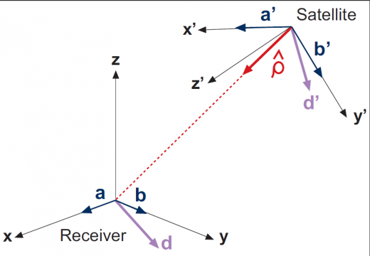
The Wind-up effect on phase measurements depends on the relative orientation of satellite and receiver antennas, and the direction of the line of sight [footnotes 1].
For a receiver with fixed coordinates, the wind-up is due to the satellite orbital motion. As the satellite moves along its orbital path it must perform a rotation to keep its solar panels pointing to the sun direction in order to obtain the maximum energy while the satellite antenna keeps pointing to the earth's centre. This rotation causes a phase variation that the receiver misunderstands as a range variation.
The wind-up correction ([math]\displaystyle{ \Delta \Phi }[/math]) due to the satellite motion can be computed from the expressions derived by [Wu et al., 1993][1] for a crossed dipole antenna:
- [math]\displaystyle{ \Delta \Phi=2N\pi+\delta \phi \qquad \mbox{(1)} }[/math]
- where [math]\displaystyle{ \delta \Phi }[/math] is the fractional part of a cycle given by
- [math]\displaystyle{ \delta \phi=sign(\zeta)\cdot \arccos \left( \frac{\vec{D}^{\prime}\cdot\vec{D}}{\|\vec{D}^{\prime}\|\cdot\|\vec{D}\|}\right) \qquad }[/math]
- with [math]\displaystyle{ \zeta=\hat{k}\cdot \left(\vec{D}^{\prime}\times\vec{D}\right) \qquad \mbox{(2)} }[/math]
- and N is an integer number given by
- [math]\displaystyle{ N=nint\left[\frac{\Delta \Phi_{previous}-\delta \Phi}{2\pi}\right] \qquad \mbox{(3)} }[/math] (N can be initialised as zero)
- where [math]\displaystyle{ \Delta \Phi_{previous} }[/math] is the previous value of phase correction, [math]\displaystyle{ nint }[/math] stands for the nearest integer and [math]\displaystyle{ D }[/math] and [math]\displaystyle{ D' }[/math] are two effective dipole for the receiver and transmitter
- [math]\displaystyle{ \begin{array}{l} \vec{D}\,=\hat{\mathbf a}\,-\,\hat{\boldsymbol \kappa}(\hat{\boldsymbol \kappa}\cdot\hat{\mathbf a})\,+\hat{\boldsymbol \kappa}\times\hat{\mathbf b}\\ \vec{D}^{\prime}=\hat{\mathbf a}^{\prime}-\hat{\boldsymbol \kappa}(\hat{\kappa}\cdot\hat{\mathbf a}^{\prime})-\hat{\boldsymbol \kappa}\times\hat{\mathbf b}^{\prime} \end{array} \qquad \mbox{(4)} }[/math]
- where the unitary vectors [math]\displaystyle{ \hat{\mathbf a} }[/math], [math]\displaystyle{ \hat{\mathbf b} }[/math], [math]\displaystyle{ \hat{\mathbf a}^{\prime} }[/math], [math]\displaystyle{ \hat{\mathbf b}^{\prime} }[/math] and [math]\displaystyle{ \hat{\boldsymbol \kappa} }[/math] are defined as follows:
Continuity between consecutive phase observations must be ensured by adding full cycle terms of [math]\displaystyle{ \pm 2\pi }[/math] to the correction (1).
- Receiver coordinate system: [math]\displaystyle{ \hat{\mathbf a} }[/math], [math]\displaystyle{ \hat{\mathbf b} }[/math]: The local Earth North Up (ENU) coordinates can be used for the receiver, and the unitary orthogonal vectors [math]\displaystyle{ \hat{\mathbf a} }[/math] and [math]\displaystyle{ \hat{\mathbf b} }[/math] be defined as pointing to the East and North.
- Satellite coordinate system: [math]\displaystyle{ \hat{\mathbf a}^{\prime} }[/math], [math]\displaystyle{ \hat{\mathbf b}^{\prime} }[/math]: The satellite-fixed-coordinate [math]\displaystyle{ (x',y',z') }[/math] frame of the Satellite Antenna Phase Centre can be used for the satellite, and the unitary orthogonal vectors [math]\displaystyle{ \hat{\mathbf a}^{\prime} }[/math] and [math]\displaystyle{ \hat{\mathbf b}^{\prime} }[/math] be defined as pointing to the [math]\displaystyle{ \hat{\mathbf i} }[/math] and [math]\displaystyle{ \hat{\mathbf j} }[/math] directions, defined by equations
- [math]\displaystyle{ \hat{\mathbf i}=\hat{\mathbf j} \times \hat{\mathbf k} }[/math]
- [math]\displaystyle{ \hat{\mathbf j}=\hat{\mathbf k} \times \hat{\mathbf e}\qquad \mbox{(5)} }[/math]
- being
- [math]\displaystyle{ \hat{\mathbf e}=\displaystyle \frac{{\mathbf r}_{_{sun}}-{\mathbf r}_{sat_{_{MC}}}}{\parallel{{\mathbf r}_{_{sun}}-{\mathbf r}_{sat_{_{MC}}}}\parallel}\qquad \mbox{(6)} }[/math][footnotes 2]
- Line of sight vector [math]\displaystyle{ \hat{\boldsymbol \kappa} }[/math]: is a unitary vector pointing from satellite to receiver.
Due to the carrier phase ambiguity, the value [math]\displaystyle{ N }[/math] can be chosen arbitrarily at the beginning of phase tracking session, and usually it is taken as zero (i.e., it is assimilated into the unknown carrier phase ambiguity).
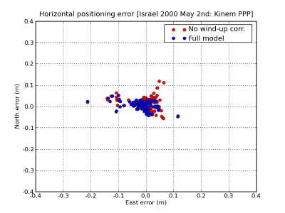
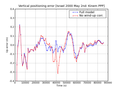
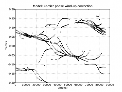
Figure 2 illustrates the effect of the carrier wind-up correction. The solution computed using the wind-up correction is shown in blue and the solution without using this correction in red. The wind-up effect on range is shown in the second row at left.
Figure 2: Carrier phase Wind-up: Range and position domain effect First row shows the horizontal (left) and vertical (right) positioning error using (blue) or not using (red) the carrier wind-up correction, equation (1). The wind-up effect on range is shown in the second row at left
Notes
- ^ Imagine that the satellite-to-receiver distance keeps fixed, but the satellite turns around [math]\displaystyle{ 360^o }[/math], the distance measured over phase would vary a wavelength, that would be approximately [math]\displaystyle{ 20 }[/math] centimetres for the GPS [math]\displaystyle{ L_1 }[/math] carrier phase measurement
- ^ The planetary ephemeris are usually given in the CRS reference frame (i.e, relative to the Aries direction. Nevertheless, given the low accuracy required for these computations (only to compute the unitary vectors), a simple rotation [math]\displaystyle{ R_3[-\theta] }[/math] of sidereal time [math]\displaystyle{ \theta }[/math] is enough to transform the CRS coordinates to the TRS (see Reference Frames in GNSS).
References
- ^ [Wu et al., 1993] Wu, J., Wu, S., Hajj, G., Bertiguer, W. and Lichten, S., 1993. Effects of Antenna Orientation on GPS Carrier Phase Measurements. Manuscripta Geodaetica. 18, pp. 91-98.


