If you wish to contribute or participate in the discussions about articles you are invited to contact the Editor
Emission Time Computation: Difference between revisions
Carlos.Lopez (talk | contribs) No edit summary |
Carlos.Lopez (talk | contribs) No edit summary |
||
| Line 14: | Line 14: | ||
The emission time can be directly obtained from the reception time, taking into account that the pseudorange <math>R</math> is a direct measurement of the time difference between both epochs, each one of them measured in the corresponding clock: | The emission time can be directly obtained from the reception time, taking into account that the pseudorange <math>R</math> is a direct measurement of the time difference between both epochs, each one of them measured in the corresponding clock: | ||
<math> | ::<math> | ||
R=c\;\left(t_{rcv}[reception]-t^{sat}[emission]\right) | R=c\;\left(t_{rcv}[reception]-t^{sat}[emission]\right) | ||
\qquad \mbox{(1)}</math> | \qquad \mbox{(1)}</math> | ||
| Line 21: | Line 21: | ||
So, the signal emission time, measured with satellite clock (<math>t^{sat}</math>), is given by: | So, the signal emission time, measured with satellite clock (<math>t^{sat}</math>), is given by: | ||
<math> | ::<math> | ||
t^{sat}[emission]=t_{rcv}[reception]-\Delta t | t^{sat}[emission]=t_{rcv}[reception]-\Delta t | ||
\qquad \mbox{(2)}</math> | \qquad \mbox{(2)}</math> | ||
| Line 28: | Line 28: | ||
where, | where, | ||
<math> | ::<math> | ||
\Delta t= R/c | \Delta t= R/c | ||
\qquad \mbox{(3)}</math> | \qquad \mbox{(3)}</math> | ||
Thence, if the <math>\delta t^{sat}</math> is the satellite clock offset, regarding to the GNSS (GPS, GLONASS, Galileo...) system time scale (see [[Clock Modelling]] the transmission time <math>T[emission]</math> in this system time scale can be computed from the receiver measurement time tags (<math>t_{rcv}</math>) as: | Thence, if the <math>\delta t^{sat}</math> is the satellite clock offset, regarding to the GNSS ([[GPS General Introduction|GPS]], [[GLONASS General Introduction|GLONASS]], [[GALILEO General Introduction|Galileo]]...) system time scale (see [[Clock Modelling]] the transmission time <math>T[emission]</math> in this system time scale can be computed from the receiver measurement time tags (<math>t_{rcv}</math>) as: | ||
<math> | ::<math> | ||
T[emission] = t^{sat}[emission] - \delta t^{sat} = t_{rcv}[reception] - R/c - \delta t^{sat} | T[emission] = t^{sat}[emission] - \delta t^{sat} = t_{rcv}[reception] - R/c - \delta t^{sat} | ||
\qquad \mbox{(4)}</math> | \qquad \mbox{(4)}</math> | ||
| Line 42: | Line 42: | ||
The former equation (4) has the advantage of providing the signal emission time directly, without iterative calculation, although it does need pseudorange measurements in order to connect both epochs. | The former equation (4) has the advantage of providing the signal emission time directly, without iterative calculation, although it does need pseudorange measurements in order to connect both epochs. | ||
The accuracy in determination of <math>T[emission]</math> is very high, and essentially depends on <math>\delta t^{sat}</math> error. For instance, in the case of the GPS system it is less than <math>10</math> or <math>100</math> nanoseconds with S/A=off and S/A=on, respectively. This allows calculating satellite coordinates with errors below one tenth of millimetre in both cases | |||
The accuracy in determination of <math>T[emission]</math> is very high, and essentially depends on <math>\delta t^{sat}</math> error. For instance, in the case of the [[GPS General Introduction|GPS]] system it is less than <math>10</math> or <math>100</math> nanoseconds with S/A=off and S/A=on, respectively. This allows calculating satellite coordinates with errors below one tenth of millimetre in both cases <ref group="footnotes">GPS, GLONASS or Galileo satellites speed is of few km/s.</ref>. | |||
==A purely geometric algorithm== | ==A purely geometric algorithm== | ||
The former algorithm (equation 2) provides the signal emission time tied to satellite clock (<math>t^{sat}</math>). The next algorithm ties this epoch to receiver clock (<math>t_{rcv}</math>): | The former algorithm (equation 2) provides the signal emission time tied to satellite clock (<math>t^{sat}</math>). The next algorithm ties this epoch to receiver clock (<math>t_{rcv}</math>): | ||
<math> | ::<math> | ||
t_{rcv}[emission]=t_{rcv}[reception]-\Delta t | t_{rcv}[emission]=t_{rcv}[reception]-\Delta t | ||
\qquad \mbox{(5)}</math> | \qquad \mbox{(5)}</math> | ||
| Line 54: | Line 57: | ||
where <math>\Delta t</math> is now calculated by iteration assuming that an approximate receptor position <math>r_{0_{rcv}}</math> is known (it converges very fast): | where <math>\Delta t</math> is now calculated by iteration assuming that an approximate receptor position <math>r_{0_{rcv}}</math> is known (it converges very fast): | ||
The algorithm is based in the following steps: | The algorithm is based in the following steps: | ||
::1. Calculate the position <math>{\mathbf r}^{sat}</math> of the satellite at signal reception time <math>t_{rcv}</math>. | |||
::2. Calculate the geometric distance between satellite coordinates obtained previously and receiver position <ref group="footnotes">Again, notice that satellite and receiver coordinates must be given in the same reference system, because satellite-receiver ray must be generated in a common reference system.</ref>, and from it, calculate the signal traveling time between both points: <math> | |||
\Delta t=\frac{\left\| {\mathbf r}^{sat}-{\mathbf r}_{0_{rcv}}\right\|}{c} \qquad \mbox{(6)}</math> | \Delta t=\frac{\left\| {\mathbf r}^{sat}-{\mathbf r}_{0_{rcv}}\right\|}{c} \qquad \mbox{(6)}</math> | ||
::3. Calculate satellite position at the time: <math>t = t_{rcv} - \Delta t \Longrightarrow r_{sat}</math>. | |||
::4. Compare the new position <math>r^{sat}</math> with the former position. If they differ more than certain threshold value, iterate the procedure starting from 2. | |||
<math> | |||
Finally, emission time at the system-time-scale is given by<ref group="footnotes">Rigorously, equation (7) is: <math>T[emission] = f(T[reception]) = f(t_{rcv}[reception] - \delta t_{rcv}) \simeq t_{rcv}[emission] - \delta t_{rcv}</math> where function <math>f(\cdot)</math> represents geometric algorithm.</ref>: | |||
::<math> | |||
T[emission] = t_{rcv}[emission] - \delta t_{rcv} \qquad \mbox{(7)}</math> | T[emission] = t_{rcv}[emission] - \delta t_{rcv} \qquad \mbox{(7)}</math> | ||
where <math>\delta t_{rcv}</math> is receiver clock offset referred to the system time, that may be obtained from navigation solution (although "a posteriori"). | where <math>\delta t_{rcv}</math> is receiver clock offset referred to the system time, that may be obtained from navigation solution (although "a posteriori"). | ||
==Comments== | ==Comments== | ||
This algorithm for the satellite coordinate calculations at the reception epoch allows an efficient modularity because pseudorange measurements are not needed to compute the transmission time. | This algorithm for the satellite coordinate calculations at the reception epoch allows an efficient modularity because pseudorange measurements are not needed to compute the transmission time. | ||
If the receiver clock offset is small <ref group= | |||
In any case, it must be taken into account that neglecting this term when <math>\delta t_{rcv}</math> reaches large values (e.g., 1 millisecond) may introduce errors of about one meter in satellite coordinates, and this must be taken in account when building the navigation model<ref group= | If the receiver clock offset is small <ref group="footnotes">Some receivers apply clock-steering adjusting their clocks epoch-by-epoch and providing offsets of few nanoseconds. However, in many cases the receiver wait until gathering an offset of <math>1</math> millisecond to adjust the clock.</ref>, thence the <math>\delta t_{rcv}</math> may be neglected. On the other hand, the receiver clock estimates from the navigation solution can be used (extrapolated from the previous epoch). In any case, it must be taken into account that neglecting this term when <math>\delta t_{rcv}</math> reaches large values (e.g., 1 millisecond) may introduce errors of about one meter in satellite coordinates, and this must be taken in account when building the navigation model<ref group="footnotes">In the "design matrix" or Jacobian matrix, obtained when linearising the model with respect to coordinates and receiver clock errors, see [[Code Based Positioning (SPP)]].</ref>; or more precisely, in the partial derivative respect to receiver clock of design matrix. | ||
{| | |||
::{| | |||
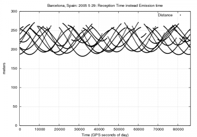
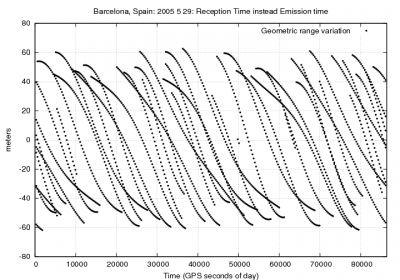
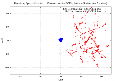
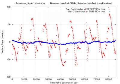
|+align="bottom"|''Figure 1:Effect of using the satellite coordinates at the reception time instead of transmission time in positioning'' | |+align="bottom"|''Figure 1:Effect of using the satellite coordinates at the reception time instead of transmission time in positioning'' | ||
| Line 86: | Line 99: | ||
Figure (1) shows an example to illustrating the effect of neglecting the | Figure (1) shows an example to illustrating the effect of neglecting the traveling time in the satellite coordinates computation for positioning. It corresponds to a receiver located in Barcelona, Spain (receiver coordinates <math>\lambda\simeq 2^o</math> <math>\phi \simeq 41^o</math>). During the <math>70</math> to <math>90</math> milliseconds of traveling time, the satellite moves about <math>200-250</math> meters, which leads to <math>+/-60</math> meters in range. The effect on the user position is up to <math>50</math> meters or more in horizontal and vertical components. | ||
==Notes== | ==Notes== | ||
<references group="footnotes"/ > | <references group="footnotes"/> | ||
[[Category:Fundamentals]] | [[Category:Fundamentals]] | ||
Revision as of 09:12, 8 August 2011
| Fundamentals | |
|---|---|
| Title | Emission Time Computation |
| Author(s) | J. Sanz Subirana, JM. Juan Zornoza and M. Hernandez-Pajares, University of Catalunia, Spain. |
| Level | Advanced |
| Year of Publication | 2011 |
Two different algorithms for the satellite transmission time computation from the receiver measurement time are presented as follows. The first of them is based on using the pseudorange measurements, which is a link between the receiver time tags (i.e., the reception time in the receiver clock) and the satellite transmission time (in the satellite clock). The second one is a pure geometric algorithm, which does not require any receiver measurement. It only needs the satellite coordinates and an approximate receiver position.
A pseudorange based algorithm
The emission time can be directly obtained from the reception time, taking into account that the pseudorange [math]\displaystyle{ R }[/math] is a direct measurement of the time difference between both epochs, each one of them measured in the corresponding clock:
- [math]\displaystyle{ R=c\;\left(t_{rcv}[reception]-t^{sat}[emission]\right) \qquad \mbox{(1)} }[/math]
So, the signal emission time, measured with satellite clock ([math]\displaystyle{ t^{sat} }[/math]), is given by:
- [math]\displaystyle{ t^{sat}[emission]=t_{rcv}[reception]-\Delta t \qquad \mbox{(2)} }[/math]
where,
- [math]\displaystyle{ \Delta t= R/c \qquad \mbox{(3)} }[/math]
Thence, if the [math]\displaystyle{ \delta t^{sat} }[/math] is the satellite clock offset, regarding to the GNSS (GPS, GLONASS, Galileo...) system time scale (see Clock Modelling the transmission time [math]\displaystyle{ T[emission] }[/math] in this system time scale can be computed from the receiver measurement time tags ([math]\displaystyle{ t_{rcv} }[/math]) as:
- [math]\displaystyle{ T[emission] = t^{sat}[emission] - \delta t^{sat} = t_{rcv}[reception] - R/c - \delta t^{sat} \qquad \mbox{(4)} }[/math]
The former equation (4) has the advantage of providing the signal emission time directly, without iterative calculation, although it does need pseudorange measurements in order to connect both epochs.
The accuracy in determination of [math]\displaystyle{ T[emission] }[/math] is very high, and essentially depends on [math]\displaystyle{ \delta t^{sat} }[/math] error. For instance, in the case of the GPS system it is less than [math]\displaystyle{ 10 }[/math] or [math]\displaystyle{ 100 }[/math] nanoseconds with S/A=off and S/A=on, respectively. This allows calculating satellite coordinates with errors below one tenth of millimetre in both cases [footnotes 1].
A purely geometric algorithm
The former algorithm (equation 2) provides the signal emission time tied to satellite clock ([math]\displaystyle{ t^{sat} }[/math]). The next algorithm ties this epoch to receiver clock ([math]\displaystyle{ t_{rcv} }[/math]):
- [math]\displaystyle{ t_{rcv}[emission]=t_{rcv}[reception]-\Delta t \qquad \mbox{(5)} }[/math]
where [math]\displaystyle{ \Delta t }[/math] is now calculated by iteration assuming that an approximate receptor position [math]\displaystyle{ r_{0_{rcv}} }[/math] is known (it converges very fast):
The algorithm is based in the following steps:
- 1. Calculate the position [math]\displaystyle{ {\mathbf r}^{sat} }[/math] of the satellite at signal reception time [math]\displaystyle{ t_{rcv} }[/math].
- 2. Calculate the geometric distance between satellite coordinates obtained previously and receiver position [footnotes 2], and from it, calculate the signal traveling time between both points: [math]\displaystyle{ \Delta t=\frac{\left\| {\mathbf r}^{sat}-{\mathbf r}_{0_{rcv}}\right\|}{c} \qquad \mbox{(6)} }[/math]
- 3. Calculate satellite position at the time: [math]\displaystyle{ t = t_{rcv} - \Delta t \Longrightarrow r_{sat} }[/math].
- 4. Compare the new position [math]\displaystyle{ r^{sat} }[/math] with the former position. If they differ more than certain threshold value, iterate the procedure starting from 2.
Finally, emission time at the system-time-scale is given by[footnotes 3]:
- [math]\displaystyle{ T[emission] = t_{rcv}[emission] - \delta t_{rcv} \qquad \mbox{(7)} }[/math]
where [math]\displaystyle{ \delta t_{rcv} }[/math] is receiver clock offset referred to the system time, that may be obtained from navigation solution (although "a posteriori").
Comments
This algorithm for the satellite coordinate calculations at the reception epoch allows an efficient modularity because pseudorange measurements are not needed to compute the transmission time.
If the receiver clock offset is small [footnotes 4], thence the [math]\displaystyle{ \delta t_{rcv} }[/math] may be neglected. On the other hand, the receiver clock estimates from the navigation solution can be used (extrapolated from the previous epoch). In any case, it must be taken into account that neglecting this term when [math]\displaystyle{ \delta t_{rcv} }[/math] reaches large values (e.g., 1 millisecond) may introduce errors of about one meter in satellite coordinates, and this must be taken in account when building the navigation model[footnotes 5]; or more precisely, in the partial derivative respect to receiver clock of design matrix.
Figure 1:Effect of using the satellite coordinates at the reception time instead of transmission time in positioning
Figure (1) shows an example to illustrating the effect of neglecting the traveling time in the satellite coordinates computation for positioning. It corresponds to a receiver located in Barcelona, Spain (receiver coordinates [math]\displaystyle{ \lambda\simeq 2^o }[/math] [math]\displaystyle{ \phi \simeq 41^o }[/math]). During the [math]\displaystyle{ 70 }[/math] to [math]\displaystyle{ 90 }[/math] milliseconds of traveling time, the satellite moves about [math]\displaystyle{ 200-250 }[/math] meters, which leads to [math]\displaystyle{ +/-60 }[/math] meters in range. The effect on the user position is up to [math]\displaystyle{ 50 }[/math] meters or more in horizontal and vertical components.
Notes
- ^ GPS, GLONASS or Galileo satellites speed is of few km/s.
- ^ Again, notice that satellite and receiver coordinates must be given in the same reference system, because satellite-receiver ray must be generated in a common reference system.
- ^ Rigorously, equation (7) is: [math]\displaystyle{ T[emission] = f(T[reception]) = f(t_{rcv}[reception] - \delta t_{rcv}) \simeq t_{rcv}[emission] - \delta t_{rcv} }[/math] where function [math]\displaystyle{ f(\cdot) }[/math] represents geometric algorithm.
- ^ Some receivers apply clock-steering adjusting their clocks epoch-by-epoch and providing offsets of few nanoseconds. However, in many cases the receiver wait until gathering an offset of [math]\displaystyle{ 1 }[/math] millisecond to adjust the clock.
- ^ In the "design matrix" or Jacobian matrix, obtained when linearising the model with respect to coordinates and receiver clock errors, see Code Based Positioning (SPP).


