If you wish to contribute or participate in the discussions about articles you are invited to contact the Editor
GNSS Measurement features and noise: Difference between revisions
Carlos.Lopez (talk | contribs) No edit summary |
Carlos.Lopez (talk | contribs) No edit summary |
||
| Line 9: | Line 9: | ||
In this article we are going to present the main features of the GNSS receiver measurements, the noise measurement, and how it affects the combinations. | In this article we are going to present the main features of the GNSS receiver measurements, the noise measurement, and how it affects the combinations. | ||
Two main features of code and carrier phase measurements nature are depicted in figure 1: While code measurements (in green) show a noisy but continuous pattern, the carrier phase track (in blue) is thinner but broken by sudden jumps. The magnitude of such jumps is always unknown, and they happen every time the receiver recovers the carrier phase lock after a signal lose. This behaviour can be summarised in the following two concepts: | Two main features of code and carrier phase measurements nature are depicted in figure 1: While code measurements (in green) show a noisy but continuous pattern, the carrier phase track (in blue) is thinner but broken by sudden jumps. The magnitude of such jumps is always unknown, and they happen every time the receiver recovers the carrier phase lock after a signal lose. This behaviour can be summarised in the following two concepts: | ||
| Line 14: | Line 15: | ||
* Code measurements are noisy but unambiguous. | * Code measurements are noisy but unambiguous. | ||
* Carrier measurements are precise but ambiguous. | * Carrier measurements are precise but ambiguous. | ||
The previous example allows introducing the distinction between two different concepts, often used as synonyms: Precision and Accuracy. | The previous example allows introducing the distinction between two different concepts, often used as synonyms: Precision and Accuracy. | ||
Precision refers to the dispersion of a measurement around a mean value (not necessarily the true one). Accuracy refers to the closeness of the measurement to the true value. In this way, notice that a measurement like the carrier phase can be highly precise, i.e., very low noise level, but extremely wrong due to the unknown bias, which can reach thousands of kilometres (in the figure the carrier phase has been shifted to fit into the plot frame). | Precision refers to the dispersion of a measurement around a mean value (not necessarily the true one). Accuracy refers to the closeness of the measurement to the true value. In this way, notice that a measurement like the carrier phase can be highly precise, i.e., very low noise level, but extremely wrong due to the unknown bias, which can reach thousands of kilometres (in the figure the carrier phase has been shifted to fit into the plot frame). | ||
| Line 24: | Line 27: | ||
The code and carrier phase measurement noise depends on different factors like the signal power, the method used for the analog-to-digital conversion, the correlation process, the design of the antenna, etc. These errors are independent for each receiver and for each signal, and can not be removed by differential techniques (differences between receivers or satellites) or by combinations of measurements. | The code and carrier phase measurement noise depends on different factors like the signal power, the method used for the analog-to-digital conversion, the correlation process, the design of the antenna, etc. These errors are independent for each receiver and for each signal, and can not be removed by differential techniques (differences between receivers or satellites) or by combinations of measurements. | ||
Figure 2 shows a comparison of code pseudorange noise for the original GPS P1 and P2 code raw measurements and their combinations.The data was collected on December 16th 2008, in Barcelona, Spain, with an Ashtec Z-XII receiver and an AT2775-42W antenna. | Figure 2 shows a comparison of code pseudorange noise for the original GPS P1 and P2 code raw measurements and their combinations.The data was collected on December 16th 2008, in Barcelona, Spain, with an Ashtec Z-XII receiver and an AT2775-42W antenna. | ||
In the plots of the figure 2, the geometry and dispersive delays have been removed by a combination of carriers (indicated within the brackets at the top of each plot) in order to allow a better visualisation of the code measurement noise. The approximate expression of <math>\sigma</math>-noise for each combination (see article [[Combination of GNSS Measurements]]), assuming uncorrelated signal noise <ref group="footnotes">The expressions are based in the following results: Given two independent random variables <math>X</math>, <math>Y</math>, and two constants <math>a</math>, <math>b</math>, then, <math>\sigma_{aX+bY}=\sqrt{a^2 \sigma^2_X+b^2\sigma^2_Y}</math>.</ref>, is also given under each plot. Notice the agreement between the noise shown in the different plots and the theoretical values derived from this simple approach, assuming the same noise in both frequencies. | In the plots of the figure 2, the geometry and dispersive delays have been removed by a combination of carriers (indicated within the brackets at the top of each plot) in order to allow a better visualisation of the code measurement noise. The approximate expression of <math>\sigma</math>-noise for each combination (see article [[Combination of GNSS Measurements]]), assuming uncorrelated signal noise <ref group="footnotes">The expressions are based in the following results: Given two independent random variables <math>X</math>, <math>Y</math>, and two constants <math>a</math>, <math>b</math>, then, <math>\sigma_{aX+bY}=\sqrt{a^2 \sigma^2_X+b^2\sigma^2_Y}</math>.</ref>, is also given under each plot. Notice the agreement between the noise shown in the different plots and the theoretical values derived from this simple approach, assuming the same noise in both frequencies. | ||
::{| | ::{| | ||
Revision as of 10:42, 5 August 2011
| Fundamentals | |
|---|---|
| Title | GNSS Measurement features and noise |
| Author(s) | J. Sanz Subirana, JM. Juan Zornoza and M. Hernandez-Pajares, University of Catalunia, Spain. |
| Level | Medium |
| Year of Publication | 2011 |
In this article we are going to present the main features of the GNSS receiver measurements, the noise measurement, and how it affects the combinations.
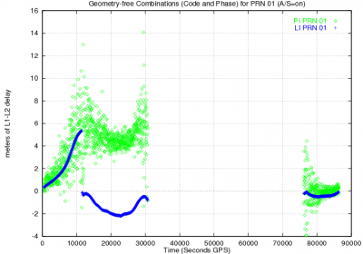
Two main features of code and carrier phase measurements nature are depicted in figure 1: While code measurements (in green) show a noisy but continuous pattern, the carrier phase track (in blue) is thinner but broken by sudden jumps. The magnitude of such jumps is always unknown, and they happen every time the receiver recovers the carrier phase lock after a signal lose. This behaviour can be summarised in the following two concepts:
- Code measurements are noisy but unambiguous.
- Carrier measurements are precise but ambiguous.
The previous example allows introducing the distinction between two different concepts, often used as synonyms: Precision and Accuracy.
Precision refers to the dispersion of a measurement around a mean value (not necessarily the true one). Accuracy refers to the closeness of the measurement to the true value. In this way, notice that a measurement like the carrier phase can be highly precise, i.e., very low noise level, but extremely wrong due to the unknown bias, which can reach thousands of kilometres (in the figure the carrier phase has been shifted to fit into the plot frame).
The code and carrier phase measurement noise depends on different factors like the signal power, the method used for the analog-to-digital conversion, the correlation process, the design of the antenna, etc. These errors are independent for each receiver and for each signal, and can not be removed by differential techniques (differences between receivers or satellites) or by combinations of measurements.
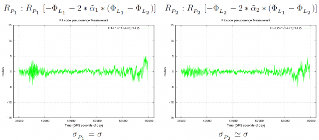
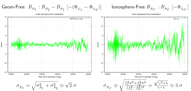
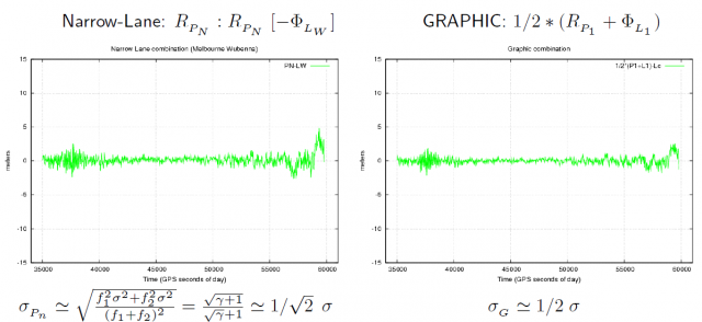
Figure 2 shows a comparison of code pseudorange noise for the original GPS P1 and P2 code raw measurements and their combinations.The data was collected on December 16th 2008, in Barcelona, Spain, with an Ashtec Z-XII receiver and an AT2775-42W antenna.
In the plots of the figure 2, the geometry and dispersive delays have been removed by a combination of carriers (indicated within the brackets at the top of each plot) in order to allow a better visualisation of the code measurement noise. The approximate expression of [math]\displaystyle{ \sigma }[/math]-noise for each combination (see article Combination of GNSS Measurements), assuming uncorrelated signal noise [footnotes 1], is also given under each plot. Notice the agreement between the noise shown in the different plots and the theoretical values derived from this simple approach, assuming the same noise in both frequencies.
Figure 2: Comparison of code pseudorange noise for the original GPS [math]\displaystyle{ R_{_{P_1}} }[/math] and [math]\displaystyle{ R_{_{P_2}} }[/math] raw code measurements and their main combinations (see captions) The geometry and the dispersive delays have been removed by a combination of carrier phases [indicated within the brackets]. The approximate expression of [math]\displaystyle{ \sigma }[/math]-noise is given above each plot. Note: [math]\displaystyle{ \tilde{\alpha}_1=\frac{1}{\gamma-1} }[/math], [math]\displaystyle{ \tilde{\alpha}_2=\gamma \, \tilde{\alpha}_1 }[/math], and [math]\displaystyle{ \gamma=(77/60)^2\simeq 1.65 }[/math]
The two main sources of receiver measurement error are presented below: Receiver noise and Multipath. For more information, please go to the following articles:
Notes
- ^ The expressions are based in the following results: Given two independent random variables [math]\displaystyle{ X }[/math], [math]\displaystyle{ Y }[/math], and two constants [math]\displaystyle{ a }[/math], [math]\displaystyle{ b }[/math], then, [math]\displaystyle{ \sigma_{aX+bY}=\sqrt{a^2 \sigma^2_X+b^2\sigma^2_Y} }[/math].


