If you wish to contribute or participate in the discussions about articles you are invited to contact the Editor
System Design Details: Difference between revisions
Jump to navigation
Jump to search
Rui.Sarnadas (talk | contribs) No edit summary |
Rui.Sarnadas (talk | contribs) No edit summary |
||
| Line 7: | Line 7: | ||
|Logo=GMV | |Logo=GMV | ||
}} | }} | ||
In order to process the [[GNSS signal|L-band signals]] transmitted from the satellites and compute the navigation solution, a GNSS receiver design can target different applications, markets, and solutions. | |||
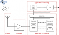
The basic structure shown in Figure 1. | |||
[[File:Receiver_Diagram.png|right|thumb|200px|'''''Figure 1:''''' General structure of a GNSS receiver system.]] | [[File:Receiver_Diagram.png|right|thumb|200px|'''''Figure 1:''''' General structure of a GNSS receiver system.]] | ||
==Block diagram== | ==Block diagram== | ||
Revision as of 11:09, 5 April 2011
| Receivers | |
|---|---|
| Title | System Design Details |
| Author(s) | GMV |
| Level | Medium |
| Year of Publication | 2011 |
In order to process the L-band signals transmitted from the satellites and compute the navigation solution, a GNSS receiver design can target different applications, markets, and solutions.
The basic structure shown in Figure 1.
Block diagram


