If you wish to contribute or participate in the discussions about articles you are invited to contact the Editor
Satellite Coordinates Computation: Difference between revisions
Carlos.Lopez (talk | contribs) |
Jaume.Sanz (talk | contribs) mNo edit summary |
||
| (5 intermediate revisions by 3 users not shown) | |||
| Line 1: | Line 1: | ||
{{Article Infobox2 | {{Article Infobox2 | ||
|Category=Fundamentals | |Category=Fundamentals | ||
|Authors=J. Sanz Subirana, J.M. Juan Zornoza and M. Hernández-Pajares, Technical University of Catalonia, Spain. | |||
|Authors= J. Sanz Subirana, | |Level=Intermediate | ||
|Level= | |||
|YearOfPublication=2011 | |YearOfPublication=2011 | ||
|Logo=gAGE | |Logo=gAGE | ||
|Title={{PAGENAME}} | |||
}} | }} | ||
Once the signal transmission time is known, the satellite coordinates may be calculated at that epoch in a given reference frame (whatever, inertial or ECEF rotating frame). Algorithms to compute such coordinates in a ECEF reference frame, from the broadcast navigation message, were given in [[GPS and Galileo Satellite Coordinates Computation]], and in [[GLONASS Satellite Coordinates Computation]]. Algorithms using precise orbits can be found in [[Precise GNSS Satellite Coordinates Computation]]. | |||
Once the signal transmission time is known, the satellite coordinates may be calculated at that epoch in a given reference frame (whatever, inertial or ECEF rotating frame). Algorithms | |||
| Line 45: | Line 44: | ||
\right ] \qquad | \right ] \qquad | ||
~~ and ~~ \qquad | ~~ and ~~ \qquad | ||
\Delta t = \frac{\sqrt{(x_{0_{rcv} | \Delta t = \frac{\sqrt{(\tilde{x}^{sat}-x_{0_{rcv}})^2+(\tilde{y}^{sat}-y_{0_{rcv}})^2+(\tilde{z}^{sat}-z_{0_{rcv}})^2}}{c} | ||
\qquad \mbox{(3)}</math> | \qquad \mbox{(3)}</math> | ||
Latest revision as of 11:53, 13 January 2013
| Fundamentals | |
|---|---|
| Title | Satellite Coordinates Computation |
| Author(s) | J. Sanz Subirana, J.M. Juan Zornoza and M. Hernández-Pajares, Technical University of Catalonia, Spain. |
| Level | Intermediate |
| Year of Publication | 2011 |
Once the signal transmission time is known, the satellite coordinates may be calculated at that epoch in a given reference frame (whatever, inertial or ECEF rotating frame). Algorithms to compute such coordinates in a ECEF reference frame, from the broadcast navigation message, were given in GPS and Galileo Satellite Coordinates Computation, and in GLONASS Satellite Coordinates Computation. Algorithms using precise orbits can be found in Precise GNSS Satellite Coordinates Computation.
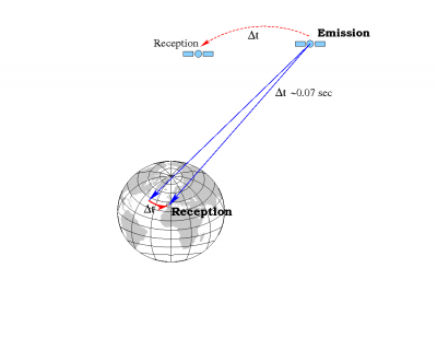
It must be taken into account that an ECEF frame is an earth-fixed system and, thence, rotates with the earth. This system must be taken at the reception time (in the GNSS time scale), because it is a common reference for all measurements (see Emission Time Computation).
An algorithm to compute the satellite coordinates at the transmission time, but referred to the ECEF tied to the earth at the reception time is given as follows:
- 1. Calculate satellite coordinates at the emission time in the associated ECEF reference frame (i.e., tied to the emission time).
- [math]\displaystyle{ T[emission] \Longrightarrow \mathbf {\tilde{r}}^{sat} \qquad \mbox{(1)} }[/math]
- Notice that, the computed coordinates are given in the ECEF frame tied to the earth at the emission time. Thence, the earth rotation during the signal travelling from the satellite to receiver must be taken into account to transform such coordinates to the adopted common ECEF frame at the reception time. This is done in the next step:
- 2. Transform satellite coordinates from the system tied to the earth at "emission time" to the system tied to the earth at "reception time" (which is common for all measurements). In order to do so, one must consider the earth rotation during the time interval [math]\displaystyle{ \Delta t }[/math] that the signal takes to propagate from the satellite to the receiver:
- [math]\displaystyle{ {\mathbf r}^{sat} = {\mathbf R}_3\left( \omega _E\Delta t\right) \cdot \tilde{\mathbf r}^{sat}\qquad \mbox{(2)} }[/math]
- where [math]\displaystyle{ R_3[\theta] }[/math] is a matrix defining a rotation of angle [math]\displaystyle{ \theta }[/math] around the [math]\displaystyle{ z }[/math]-axis:
- [math]\displaystyle{ \mathbb{\mathbf R}_3[\theta]=\left [ \begin{array}{ccc} \cos(\theta) & \sin(\theta) &0\\ -\sin(\theta) & \cos(\theta) & 0\\ 0 & 0 & 1\\ \end{array} \right ] \qquad ~~ and ~~ \qquad \Delta t = \frac{\sqrt{(\tilde{x}^{sat}-x_{0_{rcv}})^2+(\tilde{y}^{sat}-y_{0_{rcv}})^2+(\tilde{z}^{sat}-z_{0_{rcv}})^2}}{c} \qquad \mbox{(3)} }[/math]
- Note: It is advisable to calculate [math]\displaystyle{ \Delta t }[/math] using the former expression, even when pseudorange method is used to figure out signal propagation time. The reason for this is that "[math]\displaystyle{ R/c }[/math]" includes other delays (clock offsets, ...) besides just the purely geometric part [math]\displaystyle{ \rho/c }[/math]. In other words, [math]\displaystyle{ R/c }[/math] establish a very precise link between the reception time (in the receiver time tags) and the transmission time (in the satellite clock). Nevertheless, as a geometric distance it can be biased (mainly by the satellite and receiver clock offsets) by hundreds of kilometres.
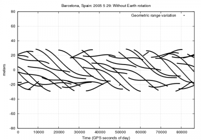
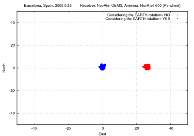
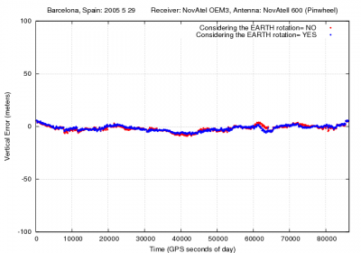
Figure 1 illustrates the effect of neglecting the earth rotation (equation 2) during the travelling time from the satellite to receiver. The effect on range is up to [math]\displaystyle{ 20 }[/math] meters. As expected, it is seen in the position, basically, as a rotation in the east direction, moving the receiver about [math]\displaystyle{ 25 }[/math] meters (receiver coordinates [math]\displaystyle{ \lambda\simeq 2^o }[/math] [math]\displaystyle{ \phi \simeq 41^o }[/math]).


