If you wish to contribute or participate in the discussions about articles you are invited to contact the Editor
BeiDou Signal Plan: Difference between revisions
(Undo revision 12115 by Filipe.Pelica (talk)) |
No edit summary |
||
| Line 27: | Line 27: | ||
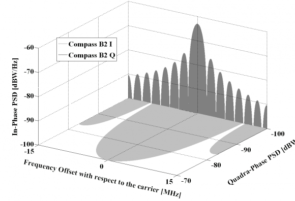
Similar to the B1 band, not all the technical aspects of the Compass signals in B2 have been defined yet. Nonetheless a proposed signal waveform has already been submitted to the ITU [Compass ITU Filing] <ref name="COMPASS_ITU"/>. Next figure shows the spectral details of the studied option. | Similar to the B1 band, not all the technical aspects of the Compass signals in B2 have been defined yet. Nonetheless a proposed signal waveform has already been submitted to the ITU [Compass ITU Filing] <ref name="COMPASS_ITU"/>. Next figure shows the spectral details of the studied option. | ||
::::[[File: | ::::[[File:Compass_Sig_Plan_Fig_3.png|none|thumb|580px|'''''Figure 3:''''' Spectra of Compass Signals in the B2 band.]] | ||
Revision as of 14:32, 7 December 2012
| Fundamentals | |
|---|---|
| Title | BeiDou Signal Plan |
| Author(s) | J.A Ávila Rodríguez, University FAF Munich, Germany. |
| Level | Advanced |
| Year of Publication | 2011 |
The current frequency filings [Compass ITU Filing] [1] for radio bands made by China to the International Telecommunications Union (ITU) indicate that it would overlay both the Galileo Public Regulated Service (PRS) and the military GPS M-code at E1/L1, as well as in the L2 band. Given the importance of these protected signals and bands, we describe next in detail the intended signal plan of Compass. Since the use that China plans to do with Compass is still unclear, the spectra will be plotted in the next figures in grey to underline this fact.
Compass B1 Band
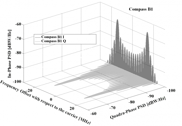
Although not all the technical aspects of the Compass signals in B1 are defined yet, an envisaged signal waveform has already been submitted to the ITU [Compass ITU Filing] [1]. Next figure shows the spectral details of the studied option in the B1 and B1-2 bands.
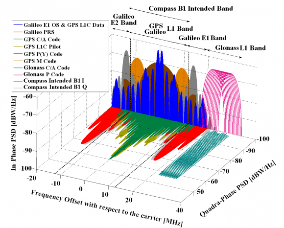
As also done in previous chapters, in order to have a better overview of all the GNSS signals around the Compass B1 band, next figure depicts the spectral environment:
It is important to note that the GPS L1C pilot and data signals are shown in quadrature in the figure although according to [GPS ICD-800][2] the final phasing is still to be decided. To conclude some technical characteristics of the Compass B1 signals are given next:
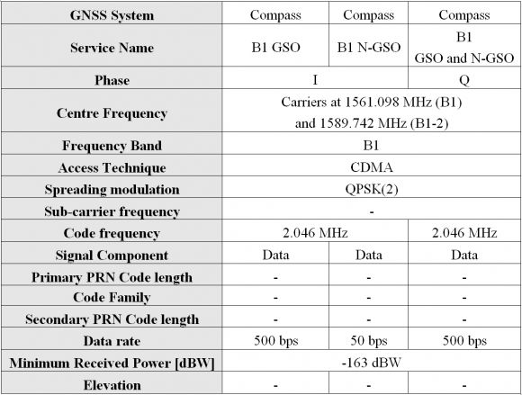 Table 1: Compass B1 signal characteristics [Compass ITU Filing] [1].
Compass B2 Band
Similar to the B1 band, not all the technical aspects of the Compass signals in B2 have been defined yet. Nonetheless a proposed signal waveform has already been submitted to the ITU [Compass ITU Filing] [1]. Next figure shows the spectral details of the studied option.
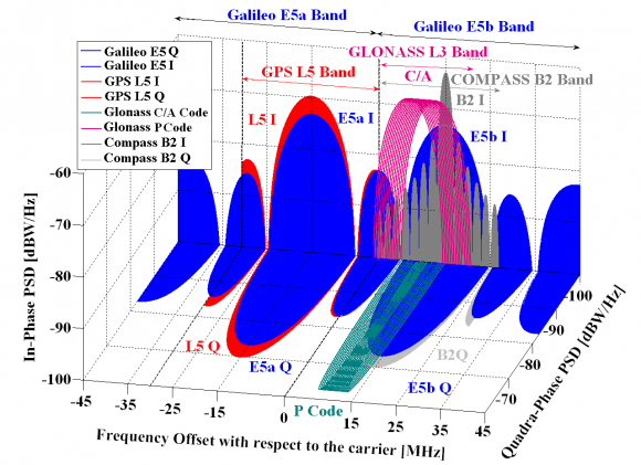
As also done for the rest of GNSS bands, we show in the next figure all the systems together.
To conclude, some technical characteristics on the Compass B2 signals are presented more in detail in the next table:
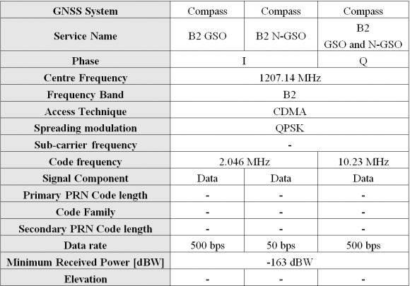 Table 2: Compass B2 signal technical characteristics [Compass ITU Filing] [1].
Compass B3 Band
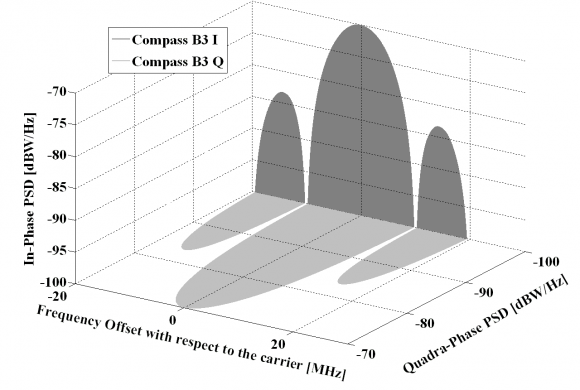
Finally, the spectral characteristics of the Compass B3 signals are also shown here. Similar to the B1 and B2 bands, not all the technical aspects of the Compass signals are defined yet. Next figure shows the Power Spectral densities of the proposed Compass signals in B3:
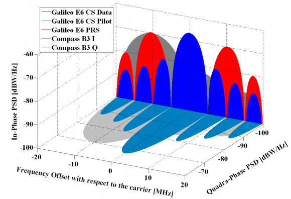
In order to have a better insight on how the Galileo E6 – Compass B3 band looks like, the following figure presents all the planned signals together.
To conclude, some technical characteristics on the Compass B3 signals are provided next [Compass ITU Filing] [1].
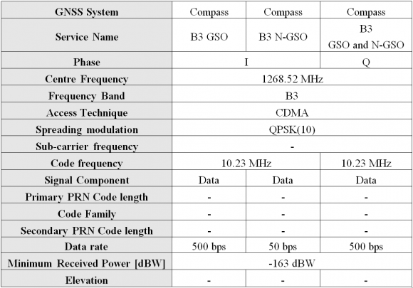 Table 3: Compass B3 signal technical characteristics [Compass ITU Filing] [1].
References
- ^ a b c d e f g [Compass ITU Filing, 2006] International Telecommunication Union, Annex 3 to Document 8D/274 on the Chinese Satellite Navigation System Compass: 8D-300 CHN Compass 1164-1215 MHz, 8D-301 CHN Compass 1260-1300 MHz, 8D-302 CHN Compass description and 8D-303 CHN Compass 1559-1610 MHz, 16 January 2006.
- ^ [GPS ICD-800, 2011] IS-GPS-800 Revision B, IS-IRN-800B-001, Navstar GPS Space Segment/User Segment L1C Interfaces, 21 September 2011.
Credits
The information presented in this NAVIPEDIA’s article is an extract of the PhD work performed by Dr. Jose Ángel Ávila Rodríguez in the FAF University of Munich as part of his Doctoral Thesis “On Generalized Signal Waveforms for Satellite Navigation” presented in June 2008, Munich (Germany)

