If you wish to contribute or participate in the discussions about articles you are invited to contact the Editor
Square-Root Raised Cosine Signals (SRRC)
| Fundamentals | |
|---|---|
| Title | Square-Root Raised Cosine Signals (SRRC) |
| Author(s) | J.A Ávila Rodríguez, University FAF Munich, Germany. |
| Level | Advanced |
| Year of Publication | 2011 |
One of the main drawbacks of all the signal waveforms is that although they can very well control the power emissions within the bandwidth of interest, they send relatively high amounts of power out of this one. A practical way of reducing the side-lobes of the spectrum of the navigation signals could be to use a Raised Cosine Filter (RCF) since this has a limited bandwidth. The Raised Cosine Filter is a particular case of Nyquist filter and is defined in the frequency domain as follows:
where [math]\displaystyle{ W-W_0 }[/math] is defined as the excess bandwidth and indicates how much the spectrum of the Raised Cosine spills over a given bandwidth [math]\displaystyle{ W_0 }[/math]. As we know, Nyquist pulses (filters) are pulses that result in no Inter Symbol Interference (ISI) at the sampling time. The Nyquist pulse-shaping criterion or Nyquist condition for zero ISI is fulfilled if
where
Indeed, this is a necessary and sufficient condition which can also be expressed as follows:
where [math]\displaystyle{ X\left(f\right) }[/math] is the Fourier transform of a generic signal x(t) and [math]\displaystyle{ T_c }[/math] the time period of the pulse. The Raised Cosine filter that we described some lines above has an equivalent representation in the time domain. This is shown to be:
Another way of expressing the excess bandwidth is by means of the roll-off factor, which is defined as follows:
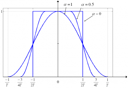
The roll-off factor indicates how much power the Raised Cosine emits above a given bandwidth [math]\displaystyle{ W_0 }[/math]. Therefore [math]\displaystyle{ 0\le \alpha \le 1 }[/math]. This can be clearly seen in the following figure for different roll-off factors:
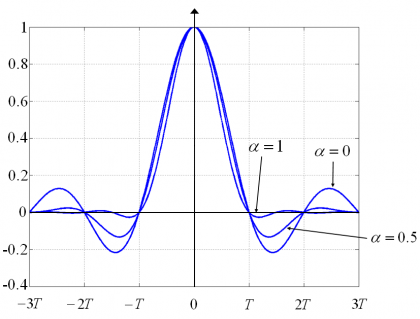
We show next the time representation [math]\displaystyle{ h_{RC}\left(t\right) }[/math] of the Raised Cosine pulses of the previous figure for different roll-off factors:
As we can recognize, the raised cosine pulse waveform with the optimum spectrum occupation ([math]\displaystyle{ \alpha = 0 }[/math]) is the pulse that also presents more oscillations in the time domain, what is a non desired characteristic in principle. In fact, low values of [math]\displaystyle{ \alpha }[/math] allow for a more efficient use of the spectrum but increase the ISI. Moreover, we have to keep in mind that none of the filters of the figures above could correspond to a real implementation since they are not causal as [math]\displaystyle{ h\left(t\right) \neq 0 }[/math] for [math]\displaystyle{ t\lt 0 }[/math]. To avoid this, a minimum delay should be added for the pulse to gain causality. Indeed, real implementations already add a delay of some chips from the moment the signal enters the filter and leaves it. This is observed in the Raised Cosine filters too.
It is important to note that a band-limited Nyquist pulse cannot avoid by itself the ISI unless the channel is ideal. This means that the RC pulses have got to be implemented together with an equalizer at the receiver for the correct identification of the symbols at the sampling time. We can express this in the following expression:
where [math]\displaystyle{ H_{TX}\left(f\right) }[/math] is the transmission filter, [math]\displaystyle{ H_C\left(f\right) }[/math] is the channel frequency response, [math]\displaystyle{ H_{RX}\left(f\right) }[/math] is the receiver filter and [math]\displaystyle{ H_E\left(f\right) }[/math] is the equalizer. The usual approach is to design the transmitter and receiver filters such that
and leave the equalizer filter to take care of the imperfections and ISI caused by the channel:
According to this, the square-root raised cosine (SRRC) pulses are Nyquist pulses of finite bandwidth with power spectral density given by:
Moreover, it can be shown that
where we can recognize that the bilateral bandwidth is finite and of value ([math]\displaystyle{ \left( 1 + \alpha \right)/T_c }[/math]). In the same manner, the time representation of such SRRC pulses is shown to adopt the following form [E.A. Lee and D.B. Messerschmitt, 1994][1]:
which is indeed a pulse shape with infinite support as we expected, since bandlimited signals extend to infinity in the time-domain. The interesting aspect of this waveform is that it satisfies the Nyquist condition for zero Inter-Symbol interference (ISI), so that the bit-error probability is identical to that of BPSK with Non Return to Zero (NRZ) pulses if the receiver samples at zero-ISI locations.
In spite of its interesting properties, the Raised Cosine Signals proposed by [R. De Gaudenzi et al., 2000][2] for Galileo presented a series of major problems that made it not recommendable for satellite navigation applications:
- One of the most important disadvantages is the fact that the RC signal is handicapped from the beginning regarding its potential improvement of performance. We have seen that the SRRC modulation makes a very efficient use of the assigned spectrum. This remains true. However, the signal is by definition band-limited to a very narrow bandwidth so that the performance could never be as good as that of other signals sharing the band with wider bandwidths. A SRRC would have been maybe the best for a narrowband receiver of around 3 MHz but Galileo would have lost the race in competitiveness as soon as other signals would have made use of wider bandwidths.
- Another consequence of the fact that the SRRC modulation is bandlimited is that its auto-correlation function has a very rounded peak. As we have seen at the beginning of this chapter, the quality of a signal improves as the slope of the ACF becomes steeper around the main peak. In the case of the Raised Cosine Signal no matter how wide the receiver bandwidth would be, we would not be able to do anything to improve the quality of our measurements. If there is something that technology shows us permanently, that is the fact that we cannot design systems thinking of today’s limitations but we must challenge our potentials.
- As shown in [R. De Gaudenzi et al., 2000][2] the receiver complexity could have profited from simplified receivers with lower complexity. While this might be true, an inherent degradation would be introduced in the system per definition since the replica signals in the receivers would be band-limited and thus handicapped. Furthermore, techniques like the narrow correlator would have brought no improvement due to the band-limited property of the SRRC pulse.
- The Raised Cosine solutions that were proposed in [R. De Gaudenzi et al., 2000][2] presented another very serious inherent problem: namely a worse antijamming protection compared with other signals, due to its spectrum concentrated in a relatively narrow bandwidth. The more spread the frequency components of a signal are, the better the resistance against narrowband and wideband interference will be (see [[GNSS Interference Model).
- Finally, the original proposal of [R. De Gaudenzi et al., 2000][2] did not contemplate the possibility of having a military signal as the PRS. Such a signal would need wide bandwidths per definition and using SRRC would have also implied important risks due to its weakness against all sources of interference.
References
- ^ [E.A. Lee and D.B. Messerschmitt, 1994] E.A. Lee and D.B. Messerschmitt, Digital Communications, 2nd edition, Norwell, Massachusetts, Kluwer Academic Publishers.
- ^ a b c d [R. De Gaudenzi et al., 2000] R. De Gaudenzi, N. Hoult, A Batchelor, G. Burden, M. Quinlan, Galileo Signal Validation Development, 2000 John Wiley & Sons, Ltd.
Credits
The information presented in this NAVIPEDIA’s article is an extract of the PhD work performed by Dr. Jose Ángel Ávila Rodríguez in the FAF University of Munich as part of his Doctoral Thesis “On Generalized Signal Waveforms for Satellite Navigation” presented in June 2008, Munich (Germany)


