If you wish to contribute or participate in the discussions about articles you are invited to contact the Editor
Satellite Antenna Phase Centre
| Fundamentals | |
|---|---|
| Title | Satellite Antenna Phase Centre |
| Author(s) | J. Sanz Subirana, J.M. Juan Zornoza and M. Hernández-Pajares, Technical University of Catalonia, Spain. |
| Level | Intermediate |
| Year of Publication | 2011 |

The broadcast ephemeris are referred to the satellite's antenna phase centre (of the ionosphere-free combination signal, see equation (6)) in a ECEF reference frame [DoD, USA, 1995][1], [GLONASS ICD, 2020] [2], and, thence, no additional correction is needed when using the navigation message. Nevertheless, the precise orbits and clocks are referred to the satellite mass centre, being necessary to account for the phase centre offset vector.
This offset is given in a satellite-fixed coordinate frame, defined by the unitary vectors [math]\displaystyle{ (\hat{\mathbf i},\hat{\mathbf j},\hat{\mathbf k}) }[/math] as follows:
- [math]\displaystyle{ \hat{\mathbf k} }[/math]: is the unit vector pointing from the Satellite Mass Centre (MC) to the earth's centre.This vector can be computed as:
- [math]\displaystyle{ \hat{\mathbf k}= -\frac{{\mathbf r}^{sat_{_{MC}}}}{\parallel{{\mathbf r}^{sat_{_{MC}}}}\parallel} \qquad\mbox{(1)} }[/math]
- where [math]\displaystyle{ {\mathbf r}^{sat_{_{MC}}} }[/math] are the satellite's mass centre coordinates in the ECEF reference frame used for such SP3 file, e.g., IGS05.
- [math]\displaystyle{ \hat{\mathbf j} }[/math]: is the resulting unit vector of the cross product of [math]\displaystyle{ \hat{\mathbf k} }[/math] vector with the unit vector from the satellite to sun. That is:
- [math]\displaystyle{ \hat{\mathbf j}=\hat{\mathbf k} \times \hat{\mathbf e} ; \qquad\mbox{being} \qquad \hat{\mathbf e}= \frac{{\mathbf r}_{_{sun}}-{\mathbf r}^{sat_{_{MC}}}}{\parallel{{\mathbf r}_{_{sun}}-{\mathbf r}^{sat_{_{MC}}}}\parallel} \qquad\mbox{(2)} }[/math]
- where the [math]\displaystyle{ {\mathbf r}_{_{sun}} }[/math] vector can be computed from the planetary ephemeris [footnotes 1][3][4].
- [math]\displaystyle{ \hat{\mathbf i} }[/math]: completes the right-handed system:
- [math]\displaystyle{ \hat{\mathbf i}=\hat{\mathbf j} \times \hat{\mathbf k} \qquad\mbox{(3)} }[/math]
Thence, if [math]\displaystyle{ {\boldsymbol \Delta}_{_{APC}} }[/math] is the antenna phase centre offset in the satellite fixed [math]\displaystyle{ (\hat{\mathbf i},\hat{\mathbf j},\hat{\mathbf k}) }[/math] system, the satellite antenna phase centre coordinates in the ECEF frame are:
- [math]\displaystyle{ {\mathbf r}^{sat_{_{APC}}}={\mathbf r}^{sat_{_{MC}}}+{\mathbf R}\cdot {\boldsymbol \Delta}_{_{APC}} \qquad\mbox{(4)} }[/math]
- where
- [math]\displaystyle{ {\mathbf R}=\left [\hat{\mathbf i}\,\,\,\hat{\mathbf j}\,\,\,\hat{\mathbf k} \right ] \qquad\mbox{(5)} }[/math]
Notice that the antenna phase centres ([math]\displaystyle{ {\boldsymbol \Delta}_{APC_{L1}} }[/math], [math]\displaystyle{ {\boldsymbol \Delta}_{APC_{L2}} }[/math]) are frequency dependent as it is shown in Figure 1.
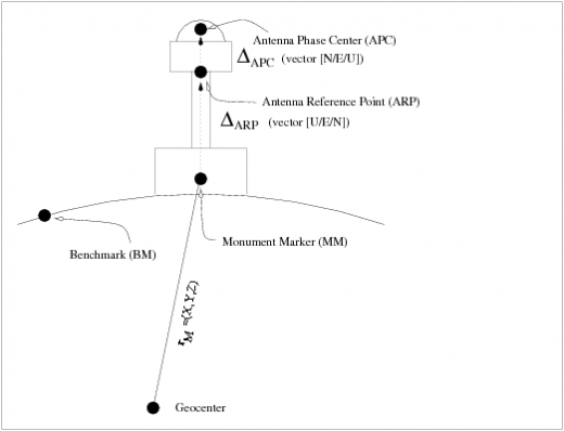
Figure 1: Layout of a permanent receiver site with indication of the Monument Marker, Antenna Reference Point and Antenna Phase Centre.

The antenna phase centre offset in the ionosphere-free combination (see Geometry-free combination in Combination of GNSS Measurements) is given by:
- [math]\displaystyle{ {\boldsymbol \Delta}_{APC_{LC}}=\frac{f_1^2 {\boldsymbol \Delta}_{APC_{L1}}-f_2^2 {\boldsymbol \Delta}_{APC_{L2}}}{f_1^2-f_2^2} \qquad\mbox{(6)} }[/math]
From November 29th 1998 (GPS week 986) to November 4th 2006 (GPS week [math]\displaystyle{ 1\,400 }[/math]), the IGS products used the following antenna phase centre offsets for the ionosphere-free combination ([math]\displaystyle{ {\boldsymbol \Delta}_{APC_{L_C}} }[/math]):
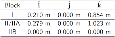
Table 1: [math]\displaystyle{ {\boldsymbol \Delta}_{APC_{LC}} }[/math] of GPS satellite used by IGS until November 4th 2006.

From November 5th 2006 on, IGS uses different antenna phase centre vectors ([math]\displaystyle{ \boldsymbol \Delta_{_{APC}} }[/math]) even within the same GPS satellite Block. These values are derived from an absolute calibration of the Antenna Phase Centre corrections (offset and PCVs, see Antenna Phase Centre, for GPS and also for GLONASS satellites are provided in the mentioned IGS ANTEX files.
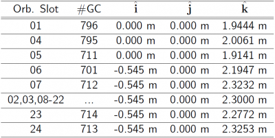
Table 2: Examples of [math]\displaystyle{ {\boldsymbol \Delta}_{APC_{LC}} }[/math] for GLONASS satellites.

The antenna phase centre corrections model (i.e., ANTEX file) associated to each precise satellite orbits and clocks SP3 file is indicated in the file header.
The Antenna Phase Centres associated to the GPS broadcast orbits and clocks can be found at the web site http://earth-info.nga.mil/GandG/sathtml/, from the National Geospatial-Intelligence Agency (NGA). An example is given in following table 3.
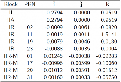
Table 3: [math]\displaystyle{ {\boldsymbol \Delta}_{APC_{LC}} }[/math] of GPS satellite used for broadcast orbits and clocks.

Figure 2 illustrates the effect of the Satellite APC correction. The navigation solution computed using the APC correction ([math]\displaystyle{ \boldsymbol \Delta_{_{APC}} }[/math]) is shown in blue and the solution without using the APC in red. The projection in range of the satellite APC offset is shown in the second row at left.
Figure 2: Satellite Antenna Phase Centre: Range and position domain effect. 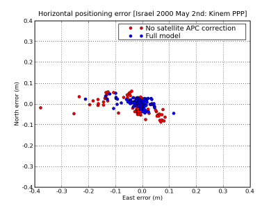
frameless 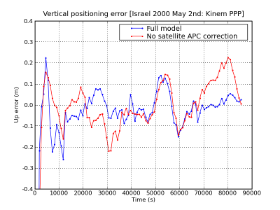
frameless 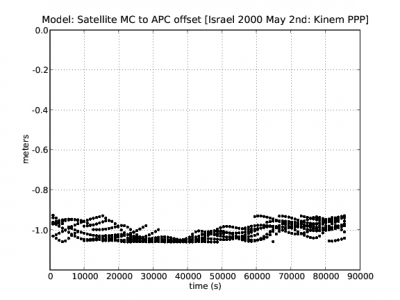
frameless First row shows the horizontal (left) and vertical (right) positioning error using (blue) or not using (red) the satellite APC correction. The variation in range is shown in the second row at left. The [math]\displaystyle{ \boldsymbol \Delta_{_{APC}} }[/math] values of table 1 have been used (data set collected on year 2002).


Notes
- ^ Simplified expressions for Solar and Lunar coordinates can be found, for instance, in [Montenbruck and Eberhard, 2005] or in GLONASS-ICD [GLONASS ICD, 1998].
References
- ^ [DoD, USA, 1995] DoD, USA, 1995. Global Positioning System Standard Positioning Service Performance Standard. http://www.navcen.uscg.gov/pubs/gps/sigspec/gpssps1.pdf.
- ^ GLONASS ICD, 2020
- ^ [Montenbruck and Eberhard, 2005] Montenbruck, O. and Eberhard, G., 2005. Satellite Orbits. Models, methods, applications. Springer, Germany.
- ^ GLONASS ICD, 1998