If you wish to contribute or participate in the discussions about articles you are invited to contact the Editor
AltBOC Modulation
| Fundamentals | |
|---|---|
| Title | AltBOC Modulation |
| Author(s) | J.A Ávila Rodríguez, University FAF Munich, Germany. |
| Level | Advanced |
| Year of Publication | 2011 |

The Alternative BOC modulation (AltBOC) is conceptually very similar to the BOC modulation but with an important difference, since contrary to BOC, AltBOC provides high spectral isolation between the two upper main lobes and the two lower main lobes (considering the I and Q phases separately). This is accomplished by using different codes for each main lobe. We can clearly see this if we remember how single band processing works [J. W. Betz, 1999][1]. Indeed, any BOC signal could be correlated with a BPSK replica having as chip rate the sub-carrier frequency of the original BOC signal. Of course the prize is the loss of power, but processing the upper or lower main lobe would make no difference since both are modulated with the same PRN code. On the other hand, if we would do the same with the AltBOC signal, we could still receive each main lobe separately since different codes would be needed. This is very interesting because AltBOC allows thus keeping the BOC implementation simple while permitting to differentiate the lobes [E. Rebeyrol et al., 2005][2]. Similar to the BOC modulation, for simplicity the AltBOC modulation is generally referred to as [math]\displaystyle{ AltBOC\left(f_s,f_c\right) }[/math] with [math]\displaystyle{ f_s=m\cdot 1.023 }[/math] and [math]\displaystyle{ f_c=n\cdot1.023 }[/math]so that commonly one only says AltBOC(m, n) for simplicity.
The Alternative BOC modulation uses a complex sub-carrier so that the spectrum is not split up, as is the case of BOC, but simply shifted to higher or lower frequencies. As per [L. Ries et al., 2003][3] the AltBOC signal is defined as the product of a PRN code sequence with a complex sub-carrier. This convention covers even and odd ratios with no necessary modification.
The AltBOC signal can be formed by two (only data signals) or four codes (data and pilot). If we have only two codes, the signal is composed of only data and can be expressed as follows:

where [math]\displaystyle{ c_s\left(t\right) }[/math] is the complex sub-carrier, complex sum of the rectangular cosine and sine-phased rectangular waveform. As we can see, this is the binary version of the complex exponential function and can be defined as follows

where [math]\displaystyle{ c_L }[/math] and [math]\displaystyle{ c_U }[/math] are the lower and upper codes respectively. As we can recognize from (1), what we are basically doing by multiplying the lower code and the upper code by the complex sub-carrier and its conjugate is approximately to shift the lower code to [math]\displaystyle{ -f_s }[/math] and the upper code to [math]\displaystyle{ +f_s }[/math]. In fact, this would be the case if we would multiply with the exponential function:

Although not exactly the same, the binary complex function is indeed a good approximation. Furthermore, AltBOC can be seen as a particular case of Multilevel Coded Spreading Symbols (MCS) with complex chip waveform. The following figure shows the spectrum (in units of Watts) of the complex sub-carrier and its conjugate. As we can see, most of the power is concentrated at the coefficients +1 and -1 and only the first 10 negative and positive coefficients are depicted in the figure (a repetition interval of 20 samples was assumed for the simulation). It is important to note that +1 and -1 corresponds in general to [math]\displaystyle{ +f_s }[/math] and [math]\displaystyle{ -f_s }[/math] after normalizing by the repetition period of the exponential function. Moreover, we can recognize that the spectrum, indeed the square of the Fourier coefficients [math]\displaystyle{ \left \Vert c_k \right \| ^2 }[/math], is normalized to integrate to 2 W of power.
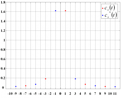
Figure 1: Spectrum [math]\displaystyle{ \left \Vert c_k \right \| ^2 }[/math] [W] of the complex sub-carrier.

If we add now the pilot channel to the definition, the general expression of the AltBOC modulation will adopt the following form:

where [math]\displaystyle{ c_L^D }[/math] is the data lower code, [math]\displaystyle{ c_L^P }[/math] the pilot lower code, [math]\displaystyle{ c_U^D }[/math] the data upper code and [math]\displaystyle{ c_U^P }[/math] the pilot upper code.
The signal defined above corresponds to the general case of the AltBOC modulation. The only problem is that by introducing a complex sub-carrier and complex codes for the data and pilot channels, the composite signal loses the constant envelope that the original BOC modulation possessed. As we have seen when we analyzed the MBOC modulation, having a constant envelope is a must since otherwise the distortion caused by the High Power Amplifier (HPA) in the satellite would not be tolerable.
In order to solve this problem, a constant envelope modified version of the AltBOC modulation was presented in [J. Godet, 2001][4]. The idea behind is to bring the phase points of the constellation back to the circle so that the amplitude of the envelope remains constant. This is achieved by introducing a new signal called Inter-Modulation (IM) product whose new terms do not contain any usable information. The modified constant envelope AltBOC [M. Soellner et al., 2003][5] and [E. D. Kaplan and C. Hegarty, 2006][6], yields:

where [math]\displaystyle{ T_s }[/math] is the period of the sub-carrier. Moreover,

and the following data and pilot sub-carriers


As we can see, while in our original conception the complex sub-carrier was composed of a cosine-phased rectangular signal for the real part and a sine-phased rectangular signal for the complex part, now both the real and complex part are a mixture of both sine and cosine delayed and early rectangular waveforms.
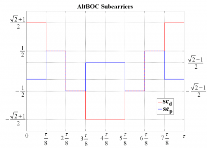
Figure 2: Shapes of data and pilot sub-carriers.

Another interesting observation is that if we take a look at the phase plots of the constant envelope AltBOC signal, we can clearly recognize that it is a classical 8-PSK modulation with a non-constant allocation of the 8 phase-states.
The power spectral density for the modified even AltBOC modulation with constant envelope is shown to be (see Power Spectral Density of the AltBOC Modulation):

while for the odd case, we have:

Finally, it is important to underline that the AltBOC modulation in its most general form does not have a constant envelope. Due to the need to have a constant envelope, slight changes were made in the multiplexing scheme and the result was the modified AltBOC modulation that we have shown in the previous lines. AltBOC can not only be understood as a signal waveform but also as a multiplexing scheme.
References
- ^ [J. W. Betz, 1999] J. W. Betz, The offset carrier modulation for GPS modernization, in Proceedings of the National Technical Meeting of the Institute of Navigation, ION-NTM 1999, pp. 639–648, January 1999, San Diego, California, USA.
- ^ [E. Rebeyrol et al., 2005] E. Rebeyrol, C. Macabiau, L. Lestarquit, L. Ries, J-L. Issler, M.L. Boucheret, M. Bousquet , BOC Power Spectrum Densities, Proceedings of the National Technical Meeting of the Institute of Navigation, ION-NTM 2005, 24-26 January 2005, Long Beach, California, USA.
- ^ [L. Ries et al., 2003] L. Ries, F. Legrand, L. Lestarquit, W. Vigneau, J.L. Issler , Tracking and Multipath Performance Assessments of BOC Signals Using a Bit-Level Signal Processing Simulator, Proceedings of the International Technical Meeting of the Institute of Navigation, ION-GNSS 2003, 9-12 September, 2003, Oregon Convention Center, Portland, Oregon, USA.
- ^ [J. Godet, 2001] J. Godet, Technical Annex to Galileo SRD Signal Plans, STF annex SRD 2001/2003 Draft 1, July 2003.
- ^ [M. Soellner et al., 2003] M. Soellner and P. Erhard, Comparison of AWGN code tracking accuracy for Alternative-BOC, Complex-LOC and Complex-BOC modulation options in Galileo E5-Band, Proceedings of the European Navigation Conference ENC-GNSS 2003, April 2003, Graz, Austria.
- ^ [E. D. Kaplan and C. Hegarty, 2006] E. D. Kaplan and C. Hegarty, Understanding GPS: Principles and Applications-2nd Edition, Chapter 4.
Credits
The information presented in this NAVIPEDIA’s article is an extract of the PhD work performed by Dr. Jose Ángel Ávila Rodríguez in the FAF University of Munich as part of his Doctoral Thesis “On Generalized Signal Waveforms for Satellite Navigation” presented in June 2008, Munich (Germany)